


5. E-axis assembly
Original Prusa i3 MK3S+ kit assembly
63
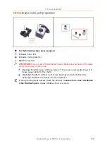
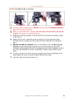
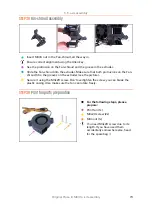
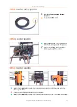
STEP 19
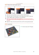
Assembling the X-carriage
Following cable management is
CRUCIAL
for the extruder
TO WORK PROPERLY!
Read the instructions carefully.
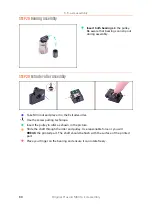
Before you assemble the X-carriage,
check the nuts in the Extruder body are still
in place
. The upper nut sometimes falls out.
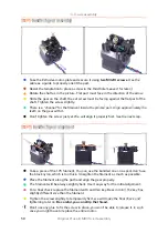
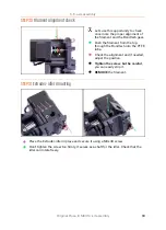
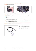
Grab the X-carriage and place it onto the back of the extruder assembly as shown
in the picture.
Make sure the motor cable follows the channel both in Extruder-body and X-
carriage. In the X-carriage the motor cable will follow the path of the IR-sensor
cable.
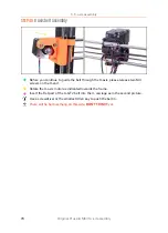
ENSURE NO WIRE IS PINCHED!
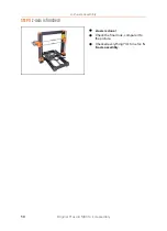
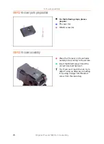
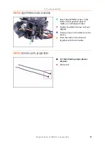
Then use the M3x10 screw and
Allen key with
ball end
to connect both parts together. If you are inserting the screw at this
moment, it will be slightly inclined in the beginning, but it will "straighten up" after
few turns. Don't tighten the screw completely, we need to adjust the IR-sensor
cable.
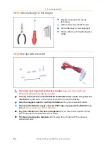
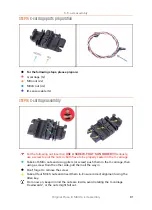
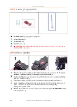
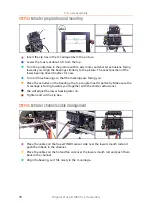
Turn the extruder to the other side and if needed insert the second M3x10 screw.
Don't tighten the screw, we need to adjust the IR-sensor cable.
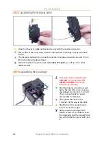
Good job! Grab one extra gummy bear ;)
Summary of Contents for i3 MK3S+
Page 6: ...6 ...
Page 7: ...Original Prusa i3 MK3S kit assembly 7 1 Introduction ...
Page 15: ...Original Prusa i3 MK3S kit assembly 15 2 Y axis assembly ...
Page 36: ...36 Original Prusa i3 MK3S kit assembly 3 X axis assembly ...
Page 44: ...44 Original Prusa i3 MK3S kit assembly 4 Z axis assembly ...
Page 51: ...Original Prusa i3 MK3S kit assembly 51 5 E axis assembly ...
Page 88: ...88 Original Prusa i3 MK3S kit assembly 6 LCD assembly ...
Page 94: ...94 Original Prusa i3 MK3S kit assembly 7 Heatbed PSU assembly ...
Page 108: ...108 Original Prusa i3 MK3S kit assembly 8 Electronics assembly ...
Page 132: ...132 Original Prusa i3 MK3S kit assembly 9 Preflight check ...
Page 137: ...137 Notes ...
Page 138: ...138 ...
Page 139: ...139 Notes ...
Page 140: ...140 ...
Page 141: ...141 Notes ...
Page 142: ...142 ...
Page 143: ...143 Notes ...
Page 144: ...144 ...