

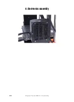


8. Electronics assembly
114
Original Prusa i3 MK3S+ kit assembly
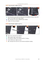
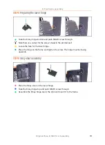
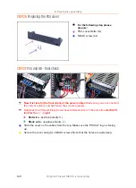
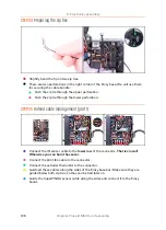
STEP 11
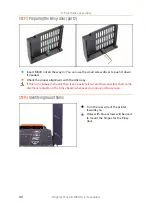
Mounting the Einsy-base (part 1)
Holes with blue arrows will be used to mount the Einsy-base.
Insert M3x10 screws in the holes and tighten them just slightly. 3-4 turns are
enough for now.
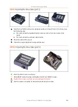
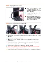
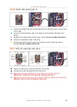
STEP 12
Mounting the Einsy-base (part 2)
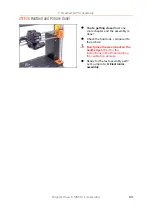
Before mounting the base on the frame, take the cable from X-axis motor (see the
yellow label) and plug it in the EINSY.
Push the textile sleeve in the slot and leave some slack of the cable along the board
(don't stretch the cable).
See the slots on the printed part, which will be used for the M3x10 screws (those
are already on the frame).
Summary of Contents for i3 MK3S+
Page 6: ...6 ...
Page 7: ...Original Prusa i3 MK3S kit assembly 7 1 Introduction ...
Page 15: ...Original Prusa i3 MK3S kit assembly 15 2 Y axis assembly ...
Page 36: ...36 Original Prusa i3 MK3S kit assembly 3 X axis assembly ...
Page 44: ...44 Original Prusa i3 MK3S kit assembly 4 Z axis assembly ...
Page 51: ...Original Prusa i3 MK3S kit assembly 51 5 E axis assembly ...
Page 88: ...88 Original Prusa i3 MK3S kit assembly 6 LCD assembly ...
Page 94: ...94 Original Prusa i3 MK3S kit assembly 7 Heatbed PSU assembly ...
Page 108: ...108 Original Prusa i3 MK3S kit assembly 8 Electronics assembly ...
Page 132: ...132 Original Prusa i3 MK3S kit assembly 9 Preflight check ...
Page 137: ...137 Notes ...
Page 138: ...138 ...
Page 139: ...139 Notes ...
Page 140: ...140 ...
Page 141: ...141 Notes ...
Page 142: ...142 ...
Page 143: ...143 Notes ...
Page 144: ...144 ...