


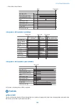


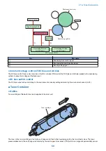


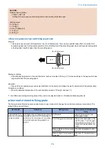
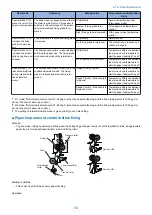

If the developing unit toner sensor (TS1) detects the absence of the toner in the developing unit, the hopper motor (M7) drives
to rotate the toner feed screw to feed toner in the sub hopper to the developing unit. Also, if the sub hopper toner sensor (TS2)
detects the absence of the toner in the sub hopper, the bottle motor (M7) drives to rotate the toner cartridge to feed the toner in
the toner cartridge to the sub hopper.
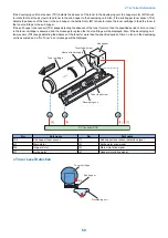
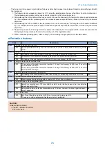
If the sub hopper toner sensor (TS2) keeps detecting the absence of the toner for more than the specified period of time, no toner
in the toner cartridge is assumed and the message to replace the toner cartridge will be displayed. Also, if the developing unit
toner sensor (TS1) keeps detecting the absence of the toner for more than the specified period of time, no toner in the developing
unit is assumed and a "No Toner" error message will be displayed.
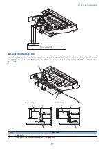
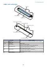
Toner cartridge
Sub hopper
Toner feed screw
Developing unit
M 1
[1]
[3]
M 6
[4]
M 7
[2]
TS2
Route of toner supply
Toner feed screw
DC Controller PCB
No.
Part name
No.
Part name
TS2
Sub hopper toner sensor
[1]
Sub hopper toner sensor detection signal
M1
Main motor
[2]
Bottle motor drive signal
M6
Hopper motor
[3]
Main motor drive signal
M7
Bottle motor
[4]
Hopper motor drive signal
● Toner Level Detection
Developing unit
TS1
TS2
Sub hopper
Toner cartridge
2. Technical Explanation
60
Summary of Contents for imageRUNNER 2525 Series
Page 1: ...Revision 9 0 imageRUNNER 2530 2525 2520 Series Service Manual ...
Page 62: ...No Part name 3 Laser unit 2 Technical Explanation 52 ...
Page 119: ...Periodical Service 3 Consumable Parts and Cleaning Parts 110 Cleaning Parts 115 ...
Page 125: ...Cleaning Parts Fixing guide Transfer guide 3 Periodical Service 115 ...
Page 136: ...List of Sensors S18 S17 S16 TS2 HU1 S9 S8 S19 TS1 S11 S12 4 Disassembly Assembly 126 ...
Page 165: ...5 Remove the idler gear 1 claw 1x 4 Disassembly Assembly 155 ...
Page 172: ... 1 4 2 3 2 2 Remove the scanner motor 4 screws 4x 4 Disassembly Assembly 162 ...
Page 186: ...3 Remove the RAM PCB Release the hook 4 Disassembly Assembly 176 ...
Page 187: ...Adjustment 5 Overview 178 Basic Adjustment 180 Adjustment when Replacing the Parts 182 ...
Page 209: ...Error Jam Alarm 7 Outline 200 Error Code 201 Jam Code 213 Alarm Code 219 ...
Page 231: ...Service Mode 8 Overview 222 Details of Service Mode 225 Remote UI Service Mode 302 ...
Page 314: ...Example of report display 8 Service Mode 304 ...
Page 387: ...APPENDICES Service Tools 378 General Circuit Diagram 379 ...