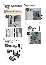


18. Install the Heater AC Harness as shown in the figure.
Attach the connector of the longest branch of the
Heater AC Harness to the cassette junction bracket
and connect the shortest branch of the Heater AC
Harness to J1106 of the Heater PCB.
• 1 Connectors
• 3 Wire saddles
1x
3x
19. In case the Cassette Heater is not installed,
disconnect the connector of the Heater AC Harness
from the Heater PCB and clamp it as shown in the
figure.
• 1 Wire saddle
1x
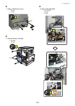
20. Install each heater.
NOTE:
After installing each heater, attach the followings;
Left cover (1 Screw) (Except for Europe model)
Left cover (2 Screws) (Only for Europe model)
Inside base cover (1 Screw (Attach it to the left cover.))
Rear lower cover (1 Screw)
Connector cover (1 Screw)
Left rear cover (3 Screws)
Left rear face cover (1 Screw)
Rear cover (right) (3 Screws)
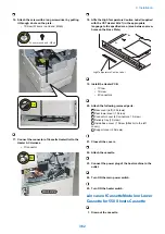
Checking after Installation
■ Disposal Parts Check
1. Following disposal parts are remained after
installation procedure.
[1] Removed face cover 1pc.
9. Installation
347
Summary of Contents for imageRUNNER 2525 Series
Page 1: ...Revision 9 0 imageRUNNER 2530 2525 2520 Series Service Manual ...
Page 62: ...No Part name 3 Laser unit 2 Technical Explanation 52 ...
Page 119: ...Periodical Service 3 Consumable Parts and Cleaning Parts 110 Cleaning Parts 115 ...
Page 125: ...Cleaning Parts Fixing guide Transfer guide 3 Periodical Service 115 ...
Page 136: ...List of Sensors S18 S17 S16 TS2 HU1 S9 S8 S19 TS1 S11 S12 4 Disassembly Assembly 126 ...
Page 165: ...5 Remove the idler gear 1 claw 1x 4 Disassembly Assembly 155 ...
Page 172: ... 1 4 2 3 2 2 Remove the scanner motor 4 screws 4x 4 Disassembly Assembly 162 ...
Page 186: ...3 Remove the RAM PCB Release the hook 4 Disassembly Assembly 176 ...
Page 187: ...Adjustment 5 Overview 178 Basic Adjustment 180 Adjustment when Replacing the Parts 182 ...
Page 209: ...Error Jam Alarm 7 Outline 200 Error Code 201 Jam Code 213 Alarm Code 219 ...
Page 231: ...Service Mode 8 Overview 222 Details of Service Mode 225 Remote UI Service Mode 302 ...
Page 314: ...Example of report display 8 Service Mode 304 ...
Page 387: ...APPENDICES Service Tools 378 General Circuit Diagram 379 ...