


1
2
3
4
5
6
7
8
9
10
1
2
3
4
5
6
7
8
9
10
F
E
D
C
B
A
F
E
D
C
B
A
P.3
SL
CL
CL
CL
CL
SL
N
.C
.
R
EG
IST
_
SN
S
L
-G
N
D
+2
4
R
2
1
L
-G
N
D
+5
R
L
-G
N
D
EXI
T
1
_
SN
S
+5
R
EXI
T
1
_
F
U
L
L
_
SN
S
1
C
_
SI
Z
E_
L
3
L
-G
N
D
C
_
SI
Z
E_
L
2
C
_
SI
Z
E_
L
1
C
_
SI
Z
E_
W
4
C
_
SI
Z
E_
W
3
L
-G
N
D
C
_
SI
Z
E_
W
2
C
_
SI
Z
E_
W
1
C
_
SI
Z
E_
L
4
+2
4
R
C
ST
_
F
EED
_
SL
_
O
N
1
2
C
ST
_
MP_
C
L
_
O
N
1
2
2
1
1
2
R
EG
IST
_
C
L
_
O
N
+2
4
R
+2
4
R
SL
EEVE_
C
L
_
O
N
+2
4
R
+2
4
R
L
-G
N
D
+3
.3
R
EN
V_
SN
S_
D
AT
A
L
-G
N
D
EN
V_
SN
S_
C
L
K
EN
V_
SN
S_
D
ET
EC
T
*
+5
R
L
-G
N
D
+5
R
L
-G
N
D
+5
R
C
ST
_
PAPER
_
SN
S
D
U
PL
EX_
C
L
_
O
N
N
.C
.
N
.C
.
D
O
O
R
_
SN
S
N
.C
.
EXI
T
1
_
SL
_
O
N
3
2
J2025
1
2
3
2
1
SL1
1
2
J225
1
2
3
4
5
J2534
1
2
3
4
5
J2536
1
2
3
4
5
1
2
3
4
5
1
2
3
4
5
6
7
8
J213
11
10
9
8
2
3
4
5
6
1
7
J212
1
2
3
J2545
1
2
3
18
17
16
15
14
13
12
11
10
9
8
2
3
4
5
6
1
7
19
J211
1
2
3
4
J2017
9
8
2
3
4
5
6
1
7
J209
1
2
3
S18
3
2
1
J2018
8
7
6
5
4
3
2
1
J299
J2029
2
1
J2028
2
1
J2027
1
2
1
2
CL2
2
1
CL3
1
2
CL1
1
2
J2432
1
2
CL4
J2535
1
2
3
4
5
1
2
3
4
5
3
2
1
J2022
1
2
3
4
5
J2020
1
2
3
4
5
J2019
S2
1
2
3
J2033
3
2
1
J2032
S12
S11
1
2
SL3
2
1
J2433
3
2
1
J2034
S5
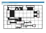
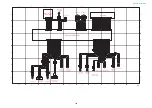
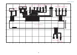
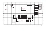
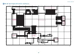
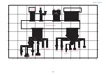
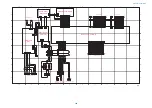
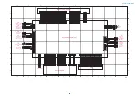
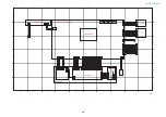
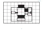
DC Controller PCB (3/4)
Enviorment Sensor
Front Cover
Open/Closed
Sensor
Pre-Registration
Sensor
Cassette 1 Paper
Sensor
Pickup Solenoid
Registration
Clutch
Developing
Cylinder
Clutch
Manual Feed
Pickup Clutch
Duplex Feed
Clutch
No.1 Delivery
Sensor
No.1 Delivery
Full Sensor
No. 1 Delivery
Reversal Solenoid
Cassette Size
Detection Switch 1
SW6
Cassette Size
Detection Switch 2
SW7
General Circuit Diagram
388
Summary of Contents for imageRUNNER 2525 Series
Page 1: ...Revision 9 0 imageRUNNER 2530 2525 2520 Series Service Manual ...
Page 62: ...No Part name 3 Laser unit 2 Technical Explanation 52 ...
Page 119: ...Periodical Service 3 Consumable Parts and Cleaning Parts 110 Cleaning Parts 115 ...
Page 125: ...Cleaning Parts Fixing guide Transfer guide 3 Periodical Service 115 ...
Page 136: ...List of Sensors S18 S17 S16 TS2 HU1 S9 S8 S19 TS1 S11 S12 4 Disassembly Assembly 126 ...
Page 165: ...5 Remove the idler gear 1 claw 1x 4 Disassembly Assembly 155 ...
Page 172: ... 1 4 2 3 2 2 Remove the scanner motor 4 screws 4x 4 Disassembly Assembly 162 ...
Page 186: ...3 Remove the RAM PCB Release the hook 4 Disassembly Assembly 176 ...
Page 187: ...Adjustment 5 Overview 178 Basic Adjustment 180 Adjustment when Replacing the Parts 182 ...
Page 209: ...Error Jam Alarm 7 Outline 200 Error Code 201 Jam Code 213 Alarm Code 219 ...
Page 231: ...Service Mode 8 Overview 222 Details of Service Mode 225 Remote UI Service Mode 302 ...
Page 314: ...Example of report display 8 Service Mode 304 ...
Page 387: ...APPENDICES Service Tools 378 General Circuit Diagram 379 ...