


• Service mode is not accessed from the Control Panel
• The remote UI is enabled in the settings on the Control Panel
[Settings/Registration] > [System Settings] > [Remote UI Settings] > [Use Remote UI] > [ON]
• The RMT-SW (remote UI service mode function) setting is enabled (set to 1) in service mode
• SERVICE MODE > SYSTEM > RMT-SW
0: OFF, 1: ON (default)
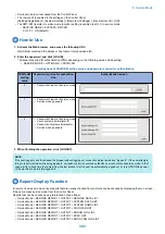
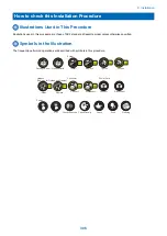
How to Use
1. Activate the Web browser, and access the following URL:
http://<Host machine's IP address or host name>/servicemode.html
2. Enter the password, and click [LOGIN].
* Password required for authentication differs depending on the following service mode setting:
• SERVICE MODE > OPTION GR. > PSWD-SW
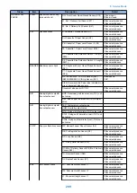
Combinations of PSWD-SW setting value and password required for authentication
PSWD-SW
setting
value
Password required for authentica-
tion
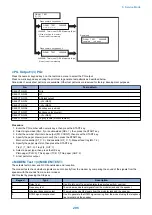
Authentication screen
0
• Password of remote UI service mode
1
• Password of remote UI service mode
• Service mode password
2
• Password of remote UI service mode
• User's system administrator ID
• Password of system administrator
• Service mode password
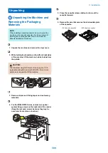
3. When finishing the operation, click [LOGOUT].
NOTE:
If the user logged in and then closed the browser without logging out, connection status remains as "logged in". If the user attempts
to log in to service mode while being logged in, exclusive control is executed so that the user cannot access service mode. In that
case, wait for a fixed time (3 minutes) from the last access to let the user be automatically logged out, or turn OFF/ON the power
of the machine to be forcibly logged off.
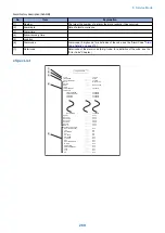
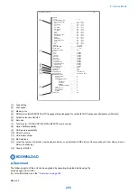
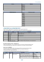
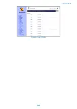
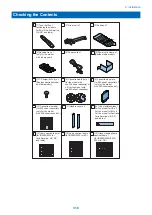
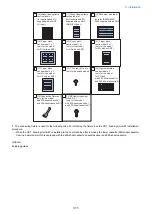
Report Display Function
In remote UI service mode, various reports that are usually checked from printouts can be checked by displaying them on screen
if the user access service mode from the Control Panel.
Reports that can be checked using this function are as follow:
• Service Mode > SERVICE REPORT > OUTPUT > SERVICE DATA LIST
• Service Mode > SERVICE REPORT > OUTPUT > SYSTEM DATA LIST
• Service Mode > SERVICE REPORT > OUTPUT > SYSTEM DUMP LIST
• Service Mode > SERVICE REPORT > OUTPUT > COUNTER LIST
• Service Mode > SERVICE REPORT > OUTPUT > ERROR LOG LIST
• Service Mode > SERVICE REPORT > OUTPUT > SPEC LIST
• Service Mode > SERVICE REPORT > OUTPUT > ERDS COM LOG LIST
8. Service Mode
303
Summary of Contents for imageRUNNER 2525 Series
Page 1: ...Revision 9 0 imageRUNNER 2530 2525 2520 Series Service Manual ...
Page 62: ...No Part name 3 Laser unit 2 Technical Explanation 52 ...
Page 119: ...Periodical Service 3 Consumable Parts and Cleaning Parts 110 Cleaning Parts 115 ...
Page 125: ...Cleaning Parts Fixing guide Transfer guide 3 Periodical Service 115 ...
Page 136: ...List of Sensors S18 S17 S16 TS2 HU1 S9 S8 S19 TS1 S11 S12 4 Disassembly Assembly 126 ...
Page 165: ...5 Remove the idler gear 1 claw 1x 4 Disassembly Assembly 155 ...
Page 172: ... 1 4 2 3 2 2 Remove the scanner motor 4 screws 4x 4 Disassembly Assembly 162 ...
Page 186: ...3 Remove the RAM PCB Release the hook 4 Disassembly Assembly 176 ...
Page 187: ...Adjustment 5 Overview 178 Basic Adjustment 180 Adjustment when Replacing the Parts 182 ...
Page 209: ...Error Jam Alarm 7 Outline 200 Error Code 201 Jam Code 213 Alarm Code 219 ...
Page 231: ...Service Mode 8 Overview 222 Details of Service Mode 225 Remote UI Service Mode 302 ...
Page 314: ...Example of report display 8 Service Mode 304 ...
Page 387: ...APPENDICES Service Tools 378 General Circuit Diagram 379 ...