


FAQ
Q1: Registration information of an E-RDS is once deleted from the UGW server, and is reregistered after that. If a communication
test is not carried out, then device information on the UGW becomes invalid.
A1: When registration of the E-RDS is deleted from the UGW, the status will be changed to that the communication test has not
completed because related information has lost from a database. So, device information will also become invalid if that condition
will be left for seven days without carrying out the communication test.
Q2: A communication test with the UGW results NG!
A2: On the conditions which have not changed a server's address or port number, the following cases can be considered in the
case where a communication test serves as NG.
1. Name resolution was failed due to an incorrect host name or DNS server has been halted.
2. Network cable is blocked off.
3. Proxy server settings is not correct.
Q3: Let me know the interval of data transmitting from E-RDS to the UGW, and what data size is sent to the UGW?
A3: The schedule of data transmitting, the start time are determined by settings in the UGW side. The timing is once per 16 hours
by default, and counter data volume could be maximum 250 bytes.
Q4: Does error-retry carry out at the time of a communication error with the UGW?
A4: The retry of SOAP communication is performed as follows. As for postAlert data, three times of data which failed transmitting
to the UGW by some external causes can be stored in RAMDISK, and will be resent at the predetermined intervals. Moreover,
the data which failed in transmission is resent at the predetermined intervals at the time of SOAP transmitting error generating
at the time of a jam log and service call log transmission.
Q5: How many log-data can be stored?
A5: Up to 5 log records can be accumulated. The data size of error information is maximum 128 bytes.
Q6: Although Microsoft ISA as a proxy server is introduced, the authentication check is failed. Can E-RDS adopt with Microsoft
ISA?
A6: "Integrated" authentication is used for Microsoft ISA though, E-RDS must comply with "Basic." Therefore if you can change
to "Basic" authentication on the server, the authentication with E-RDS can be done.
Q7: Can I turn the device power off during the e-Maintenance/ imageWARE Remote system operation?
A7: While operating the e-Maintenance/ imageWARE Remote system, the power of the device must be ON. If power OFF is
needed, do not leave the device power OFF for long time. It will become "Device is busy, try later" errors if the power supply of
network equipment such as HUB is made prolonged OFF.
Q8: Describe about the behavior of E-RDS while enabling the Real Deep Sleep functionality.
A8: While being in Real Deep Sleep, and if data to be sent is in E-RDS, the system wakes up asleep, then starts to send the data
to the UGW. The system also waits for completion of data transmission and let the device to shift to asleep status again. However,
transition time to the Real Deep Sleep depends on the device, and the transition to sleep won't be done if the next data
transmission will be done within 10 minutes.
Q9: Is E-RDS compatible with Section counter (Department counter)?
A9: No, E-RDS does not support Section counter.
Q10: Is E-RDS operation possible to a device which used IPv6?
A10: It depends on UGW side, however IPv6 has not been supported by UGW3.0.
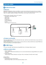
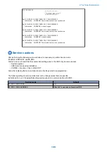
Troubleshooting
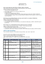
When the communication test with UGW is NG, trouble shooting is performed according to the following steps.
No.1 A communication test (COM-TEST) results NG
2. Technical Explanation
103
Summary of Contents for imageRUNNER 2525 Series
Page 1: ...Revision 9 0 imageRUNNER 2530 2525 2520 Series Service Manual ...
Page 62: ...No Part name 3 Laser unit 2 Technical Explanation 52 ...
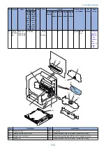
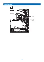
Page 119: ...Periodical Service 3 Consumable Parts and Cleaning Parts 110 Cleaning Parts 115 ...
Page 125: ...Cleaning Parts Fixing guide Transfer guide 3 Periodical Service 115 ...
Page 136: ...List of Sensors S18 S17 S16 TS2 HU1 S9 S8 S19 TS1 S11 S12 4 Disassembly Assembly 126 ...
Page 165: ...5 Remove the idler gear 1 claw 1x 4 Disassembly Assembly 155 ...
Page 172: ... 1 4 2 3 2 2 Remove the scanner motor 4 screws 4x 4 Disassembly Assembly 162 ...
Page 186: ...3 Remove the RAM PCB Release the hook 4 Disassembly Assembly 176 ...
Page 187: ...Adjustment 5 Overview 178 Basic Adjustment 180 Adjustment when Replacing the Parts 182 ...
Page 209: ...Error Jam Alarm 7 Outline 200 Error Code 201 Jam Code 213 Alarm Code 219 ...
Page 231: ...Service Mode 8 Overview 222 Details of Service Mode 225 Remote UI Service Mode 302 ...
Page 314: ...Example of report display 8 Service Mode 304 ...
Page 387: ...APPENDICES Service Tools 378 General Circuit Diagram 379 ...