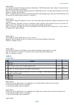


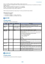


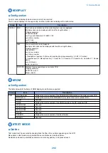


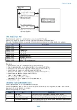
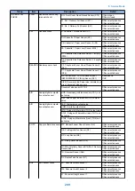


Alarm history description(ALARM)
No.
Item
Explanation
[1]
Number
The larger the number of a alarm, the more recently it has occurred.
[2]
Alarm date
Date of alarm occurrence
[3]
Alarm time
[4]
Alarm recovery time
[5]
Location
[6]
Alarm code
Alarm code (4-digit code; for a definition of the code, see the "Alarm Code"
)
[7]
Detail code
Detail code of the alarm code (8-digit code; for a definition of the code, see the
"Error Code" Chapter.)
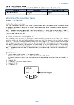
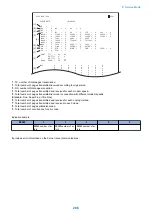
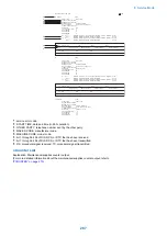
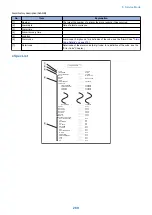
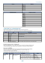
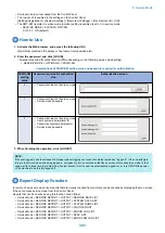
● Spec List
*****************************
*** SPEC REPORT ***
*****************************
2009 10/09 16:31
0001
TYPE
LBP SPEED
TOTAL MEMORY
MAIN
OPTION
BOOT
LANG
LANG LIBRARY
LANG FILE
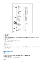
VIENTNAMESE
CHINESE(TRAD. )
TURKISH
SWEDISH
BULGARIAN
ECONT
OPT-CAS 1
OPT-CAS 2
OPT-CAS 3
OPT-DUP
OPT-FIN
MEDIA
ACTIBAT FUNCTION
BDL-IMAGE (1200)
FAX
NETWORK
PCL
PC-SCAN
BW-SEND
CL-SEND
PAF
BDL-IMAGE (600)
E-RDS
BAR-DIMM
SERCHABLE PDF
eAM
eLA
PS
_ _ _ _ _
_ _ _ _ _
_ _ _ _ _
_ _ _ _ _
_ _ _ _ _
_ _ _ _ _
_ _ _ _ _
_ _ _ _ _
_ _ _ _ _
_ _ _ _ _
_ _ _ _ _
_ _ _ _ _
_ _ _ _ _
_ _ _ _ _
_ _ _ _ _
_ _ _ _ _
_ _ _ _ _
_ _ _ _ _
_ _ _ _ _
_ _ _ _ _
_ _ _ _ _
_ _ _ _ _
_ _ _ _ _
_ _ _ _ _
_ _ _ _ _
_ _ _ _ _
_ _ _ _ _
_ _ _ _ _
_ _ _ _ _
_ _ _ _ _
_ _ _ _ _
_ _ _ _ _
_ _ _ _ _
_ _ _ _ _
_ _ _ _ _
JAPAN
45cpm
256MB
WLaa-07-09
BOOT-V0023
00000010
00000010
00000010
00000010
00000010
00000010
0303
0000
0000
0000
0000
0000
0000
OFF
ON
ON
ON
ON
OFF
OFF
OFF
OFF
OFF
OFF
OFF
OFF
OFF
OFF
[1]
[2]
[3]
[4]
[5]
8. Service Mode
289
Summary of Contents for imageRUNNER 2525 Series
Page 1: ...Revision 9 0 imageRUNNER 2530 2525 2520 Series Service Manual ...
Page 62: ...No Part name 3 Laser unit 2 Technical Explanation 52 ...
Page 119: ...Periodical Service 3 Consumable Parts and Cleaning Parts 110 Cleaning Parts 115 ...
Page 125: ...Cleaning Parts Fixing guide Transfer guide 3 Periodical Service 115 ...
Page 136: ...List of Sensors S18 S17 S16 TS2 HU1 S9 S8 S19 TS1 S11 S12 4 Disassembly Assembly 126 ...
Page 165: ...5 Remove the idler gear 1 claw 1x 4 Disassembly Assembly 155 ...
Page 172: ... 1 4 2 3 2 2 Remove the scanner motor 4 screws 4x 4 Disassembly Assembly 162 ...
Page 186: ...3 Remove the RAM PCB Release the hook 4 Disassembly Assembly 176 ...
Page 187: ...Adjustment 5 Overview 178 Basic Adjustment 180 Adjustment when Replacing the Parts 182 ...
Page 209: ...Error Jam Alarm 7 Outline 200 Error Code 201 Jam Code 213 Alarm Code 219 ...
Page 231: ...Service Mode 8 Overview 222 Details of Service Mode 225 Remote UI Service Mode 302 ...
Page 314: ...Example of report display 8 Service Mode 304 ...
Page 387: ...APPENDICES Service Tools 378 General Circuit Diagram 379 ...