


1. Clear the DC controller settings and counters.
Enter the service mode, and Then select the following:
CLEAR > ENGINE > ENGINE BKRAMCLK (Clearing of the RAM on the DC controller PCB)
2. Turn OFF and then ON the main power switch. (Turning OFF/ON the main power switch clears the RAM.)
3. If uploading of backup data fails before replacement due to the damage to the DC controller PCB, enter the values
of service mode items recorded on the service label. Since the values recorded on the service label may be outdated,
check the service mode item list (#SERVICE DATA LIST) printed out in advance, and then enter the latest values.
4. Turn OFF and then ON the main power switch. (Turning OFF/ON the main power switch allows the values entered
for the service mode items to take effect.)
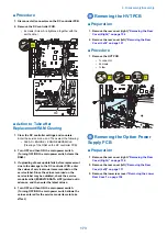
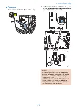
■ Action to Take after Replacing the RAM
CAUTION:
The ADRAM is powered from the secondary battery unit to back up the image memory even after the main power switch
is turned OFF and the power plug is removed from the outlet.
If the SW3 on the main controller PCB is pressed with the image backed up, the entire data stored in the memory is cleared.
Be sure to output the data stored in the memory before pressing the SW3.
Laser Exposure System
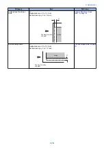
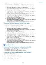
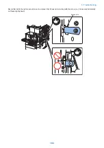
■ Action to Take after Replacing the Laser Scanner Unit
When replacing the Laser Unit, enter the value obtained by adding 1,000 to the number shown on the label affixed to the side of
the newly replaced Laser Unit in the corresponding service mode as shown below.
(Examples: If the number on the service label is 3, enter 1,003. If the number on the service label is -1, enter 999.)
145
146
147
136
148
149
150
SW No.
-67
-5
-4
-5
0
0
0
• PRINT > Bitswitch > 136 Laser horizontal scanning direction write position adjustment(A)
• PRINT > Bitswitch > 145 Laser horizontal scanning direction magnification ratio adjustment(A-B)
• PRINT > Bitswitch > 146 Laser horizontal scanning direction magnification ratio adjustment(A-C)
• PRINT > Bitswitch > 147 Laser horizontal scanning direction magnification ratio adjustment(A-D)
• PRINT > Bitswitch > 148 Laser horizontal scanning direction write position adjustment(A-B)
• PRINT > Bitswitch > 149 Laser horizontal scanning direction write position adjustment(A-C)
• PRINT > Bitswitch > 150 Laser horizontal scanning direction write position adjustment(A-D)
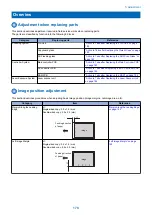
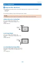
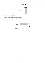
5. Adjustment
184
Summary of Contents for imageRUNNER 2525 Series
Page 1: ...Revision 9 0 imageRUNNER 2530 2525 2520 Series Service Manual ...
Page 62: ...No Part name 3 Laser unit 2 Technical Explanation 52 ...
Page 119: ...Periodical Service 3 Consumable Parts and Cleaning Parts 110 Cleaning Parts 115 ...
Page 125: ...Cleaning Parts Fixing guide Transfer guide 3 Periodical Service 115 ...
Page 136: ...List of Sensors S18 S17 S16 TS2 HU1 S9 S8 S19 TS1 S11 S12 4 Disassembly Assembly 126 ...
Page 165: ...5 Remove the idler gear 1 claw 1x 4 Disassembly Assembly 155 ...
Page 172: ... 1 4 2 3 2 2 Remove the scanner motor 4 screws 4x 4 Disassembly Assembly 162 ...
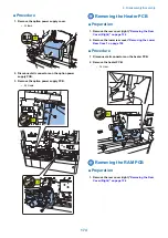
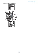
Page 186: ...3 Remove the RAM PCB Release the hook 4 Disassembly Assembly 176 ...
Page 187: ...Adjustment 5 Overview 178 Basic Adjustment 180 Adjustment when Replacing the Parts 182 ...
Page 209: ...Error Jam Alarm 7 Outline 200 Error Code 201 Jam Code 213 Alarm Code 219 ...
Page 231: ...Service Mode 8 Overview 222 Details of Service Mode 225 Remote UI Service Mode 302 ...
Page 314: ...Example of report display 8 Service Mode 304 ...
Page 387: ...APPENDICES Service Tools 378 General Circuit Diagram 379 ...