


Overview
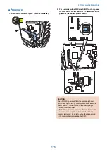
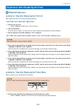
Adjustment when replacing parts
This section describes adjustment required in field service works when replacing parts.
The parts are classified by function into the following 3 blocks.
Category
Replacing parts
Reference
Scanning System
CIS Unit
“Action to Take after Replacing the CIS Unit” on page
182
Copyboard glass
“Action to Take after Replacing the Platen Glass” on page
182
ADF reading glass
“Action to Take after Replacing the ADF Scan Glass” on
page 183
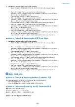
Controller System
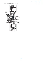
Main controller PCB
“Action to Take after Replacing theMain Controller PCB”
on page 183
DC controller PCB
“Action to Take when Replacing the DC Controller PCB”
on page 183
RAM PCB
“Action to Take after Replacing the RAM” on page 184
Laser Exposure System Laser scanner unit
“Action to Take after Replacing the Laser Scanner Unit”
on page 184
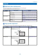
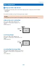
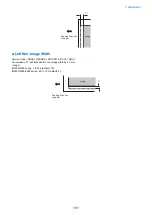
Image position adjustment
This section describes procedures when adjusting basic image position (image margins, nonimage area, etc).
Category
Item
Reference
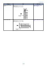
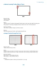
Margin Along the Leading
Edge
L1:
Single-sided copy: 2.5 ± 1.5 (mm)
Double-sided copy: 2.5 ± 2.0 (mm)
image
L1
Feeding direction
of paper
“Margin Along the Leading Edge”
on page 180
Left Image Margin
L1:
Single-sided copy: 2.5 ± 1.5 (mm)
Double-sided copy: 2.5 ± 2.0 (mm)
Feeding direction
of paper
L
1
image
“Left Image Margin” on page
180
5. Adjustment
178
Summary of Contents for imageRUNNER 2525 Series
Page 1: ...Revision 9 0 imageRUNNER 2530 2525 2520 Series Service Manual ...
Page 62: ...No Part name 3 Laser unit 2 Technical Explanation 52 ...
Page 119: ...Periodical Service 3 Consumable Parts and Cleaning Parts 110 Cleaning Parts 115 ...
Page 125: ...Cleaning Parts Fixing guide Transfer guide 3 Periodical Service 115 ...
Page 136: ...List of Sensors S18 S17 S16 TS2 HU1 S9 S8 S19 TS1 S11 S12 4 Disassembly Assembly 126 ...
Page 165: ...5 Remove the idler gear 1 claw 1x 4 Disassembly Assembly 155 ...
Page 172: ... 1 4 2 3 2 2 Remove the scanner motor 4 screws 4x 4 Disassembly Assembly 162 ...
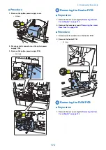
Page 186: ...3 Remove the RAM PCB Release the hook 4 Disassembly Assembly 176 ...
Page 187: ...Adjustment 5 Overview 178 Basic Adjustment 180 Adjustment when Replacing the Parts 182 ...
Page 209: ...Error Jam Alarm 7 Outline 200 Error Code 201 Jam Code 213 Alarm Code 219 ...
Page 231: ...Service Mode 8 Overview 222 Details of Service Mode 225 Remote UI Service Mode 302 ...
Page 314: ...Example of report display 8 Service Mode 304 ...
Page 387: ...APPENDICES Service Tools 378 General Circuit Diagram 379 ...