


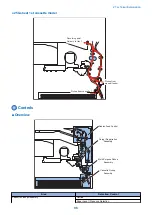


Width
Length
Width detection
Length detection
①
②
③
④
①
②
③
④
LDR
279.4
431.8
0
ON
ON
0
0
0
ON
ON
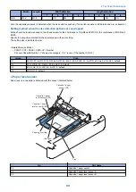
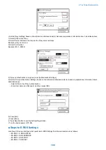
Also, the cassette presence is detected when the size switch is pushed. (If no switch is pushed, it is determined as no cassette.)
Setting method when the size detection patterns are overlapped
Size should be found manually on the check screen for the combination of A5-Rand STMT-R or the combination of B5-R and
EXEC.
Specify the ecognition method for the special paper with user setting.
The setting size is indicated below.
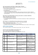
<Related Service Mode>
• PRINT> CST> CASX> CSTX-UY> Number
X shows Cassette Number. Y shows size category. (X, Y is one of the number 1/2/3/4.)
U-size.
Size
U1
26: OFI, 27: E-OFI, 37: M-OFI, 36: A-OFI, 24: FLSP, 25: A-FLSP, 30: A-LTRR, 42: FA4, 34: G-LGL 0: default
U2
32: G-LTR-R, 34: G-LGL, 23: K-LGL-R, 0: default
U3
22: K-LGL, 31: G-LTR, 29: A-LTR, 0: default
U4
28: B-OFI, 0: default
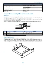
● Paper level sensor
This machine does not have the paper level sensor in the cassette.
This machine has the cassette 1 paper sensor (S2) to detect the paper.
Cassette 1 Paper Sensor (S2)
Flag
Cassette paper sensor
Paper level
Display
OFF
paper presence
ON
paper absent
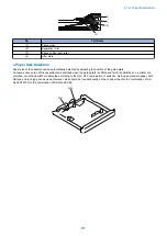
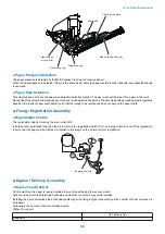
■ Multi-Purpose Pickup Assembly
● Overview
The paper in the tray of the manual feed pickup unit is forced against the manual feed pickup roller by the work of the pickup
guide plate, and only a single sheet of paper is separated and moved into the machine by the work of the manual feed pickup
roller and the separation pad.
2. Technical Explanation
93
Summary of Contents for imageRUNNER 2525 Series
Page 1: ...Revision 9 0 imageRUNNER 2530 2525 2520 Series Service Manual ...
Page 62: ...No Part name 3 Laser unit 2 Technical Explanation 52 ...
Page 119: ...Periodical Service 3 Consumable Parts and Cleaning Parts 110 Cleaning Parts 115 ...
Page 125: ...Cleaning Parts Fixing guide Transfer guide 3 Periodical Service 115 ...
Page 136: ...List of Sensors S18 S17 S16 TS2 HU1 S9 S8 S19 TS1 S11 S12 4 Disassembly Assembly 126 ...
Page 165: ...5 Remove the idler gear 1 claw 1x 4 Disassembly Assembly 155 ...
Page 172: ... 1 4 2 3 2 2 Remove the scanner motor 4 screws 4x 4 Disassembly Assembly 162 ...
Page 186: ...3 Remove the RAM PCB Release the hook 4 Disassembly Assembly 176 ...
Page 187: ...Adjustment 5 Overview 178 Basic Adjustment 180 Adjustment when Replacing the Parts 182 ...
Page 209: ...Error Jam Alarm 7 Outline 200 Error Code 201 Jam Code 213 Alarm Code 219 ...
Page 231: ...Service Mode 8 Overview 222 Details of Service Mode 225 Remote UI Service Mode 302 ...
Page 314: ...Example of report display 8 Service Mode 304 ...
Page 387: ...APPENDICES Service Tools 378 General Circuit Diagram 379 ...