


OFF
OFF
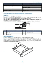
Paper
Cassette 1 Paper
Level Sensor B
Cassette 1 Paper Level Sensor A
OFF ON
Paper
Paper
Paper tray
Cassette 1 Paper Sensor
Flag
ON
ON
Cassette 1 Paper
Level Sensor B
Cassette 1 Paper
Level Sensor B
Cassette 1 Paper Level Sensor A
Cassette 1 Paper Level Sensor A
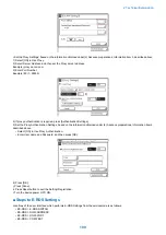
If the paper is full
If the paper is approx.half
If the paper is a little
If the paper is absent
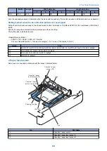
Cassette 1
paper level
sensor A
Cassette 1
paper level
sensor B
Cassette 1
paper sensor
Paper level
Display
OFF
OFF
OFF
100% to 50%
ON
OFF
OFF
50% to 50 sheets
ON
ON
OFF
50 sheet or less
---
---
ON
no paper
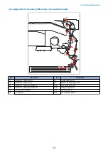
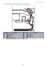
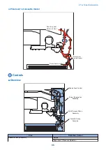
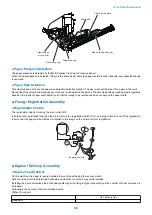
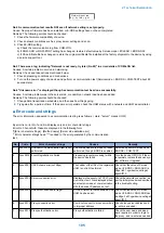
■ Cassette Pickup Assembly (250-sheet 1st cassette model)
● Overview
The paper inside the cassette is held up by the lifter plate.
When pickup takes place, the pickup solenoid (SL1) is turned on, and the pickup roller rotates once. When the pickup roller comes
into contact with the surface of paper, the sheet is picked up by rotation of the roller.
Only a single sheet of paper picked up is moved to the feed path by the separation pad, and moved as far as the registration
roller by the pickup vertical path roller.
The pickup vertical path roller and pickup roller are driven by the cassette pickup motor (M1).
2. Technical Explanation
90
Summary of Contents for imageRUNNER 2525 Series
Page 1: ...Revision 9 0 imageRUNNER 2530 2525 2520 Series Service Manual ...
Page 62: ...No Part name 3 Laser unit 2 Technical Explanation 52 ...
Page 119: ...Periodical Service 3 Consumable Parts and Cleaning Parts 110 Cleaning Parts 115 ...
Page 125: ...Cleaning Parts Fixing guide Transfer guide 3 Periodical Service 115 ...
Page 136: ...List of Sensors S18 S17 S16 TS2 HU1 S9 S8 S19 TS1 S11 S12 4 Disassembly Assembly 126 ...
Page 165: ...5 Remove the idler gear 1 claw 1x 4 Disassembly Assembly 155 ...
Page 172: ... 1 4 2 3 2 2 Remove the scanner motor 4 screws 4x 4 Disassembly Assembly 162 ...
Page 186: ...3 Remove the RAM PCB Release the hook 4 Disassembly Assembly 176 ...
Page 187: ...Adjustment 5 Overview 178 Basic Adjustment 180 Adjustment when Replacing the Parts 182 ...
Page 209: ...Error Jam Alarm 7 Outline 200 Error Code 201 Jam Code 213 Alarm Code 219 ...
Page 231: ...Service Mode 8 Overview 222 Details of Service Mode 225 Remote UI Service Mode 302 ...
Page 314: ...Example of report display 8 Service Mode 304 ...
Page 387: ...APPENDICES Service Tools 378 General Circuit Diagram 379 ...