


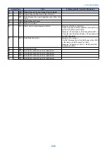


Ecode
Detail Code
Item
Description
E567
0001
Remedy
1.Replace the Shift Roller Release Sensor (S3).
2.Replace the Shift Roller Release Motor (M5).
3.Replace the Finisher Controller PCB (PCB1).
E567
0002
Title
Shift Roller Release Motor (M5) error
Description
The shift roller does not return to the shift roller release home po-
sition when the Shift Roller Release Motor (M5) has been driven
for 0.06 sec.
Remedy
1.Replace the Shift Roller Release Sensor (S3).
2.Replace the Shift Roller Release Motor (M5).
3.Replace the Finisher Controller PCB (PCB1).
E56F
0001
Title
Entrance Roller Release/Stopper HP Motor fails to move from HP
Description
At initial rotation, when the Motor rotates for specified period of
time and cannot move from HP, it is detected as an error if the
same symptom occurs again after the first retry.
Remedy
1. Check if the Motor (M6) Connector is physically removed.
2. Replace the Motor.
3. Check if the Entrance Roller Release/Stopper HP Sensor (S5)
Connector is physically removed.
4. Replace the Entrance Roller Release/Stopper HP Sensor (S5).
E56F
0002
Title
Entrance Roller Release/Stopper HP Motor fails to return to HP
Description
At initial rotation, when the Motor rotates for specified period of
time and cannot return to HP, it is detected as an error if the same
symptom occurs again after the first retry.
Remedy
1. Check if the Motor (M6) Connector is physically removed.
2. Replace the Motor.
3. Check if the Entrance Roller Release/Stopper HP Sensor (S5)
Connector is physically removed.
4. Replace the Entrance Roller Release/Stopper HP Sensor (S5).
E571
0001
Title
Gripper Open/Close Motor (M7) error
Description
The gripper unit does not leave the gripper unit home position when
the Gripper Open/Close Motor (M7) has been driven for 0.25 sec-
onds.
Remedy
1.Replace the Grip Arm Sensor (S13).
2.Replace the Gripper Open/Close Motor (M7).
3.Replace the Finisher Controller PCB (PCB1).
E571
0002
Title
Gripper Open/Close Motor (M7) error
Description
The gripper unit does not return to the gripper unit home position
when the Gripper Open/Close Motor (M7) has been driven for 0.15
seconds.
Remedy
1.Replace the Grip Arm Sensor (S13).
2.Replace the Gripper Open/Close Motor (M7).
3.Replace the Finisher Controller PCB (PCB1).
E575
0001
Title
Gripper Unit Move Motor (M2) error
Description
The gripper unit does not leave the gripper unit home position when
the Gripper Unit Move Motor (M2) has been driven for 3.8 seconds.
Remedy
1.Replace the Gripper Unit HP Sensor (S7).
2.Replace the Gripper Unit Move Motor (M2).
3.Replace the Finisher Controller PCB (PCB1).
E575
0002
Title
Gripper Unit Move Motor (M2) error
Description
The gripper unit does not return to the gripper unit home position
when the Gripper Unit Move Motor (M2) has been driven for 0.1
seconds.
Remedy
1.Replace the Gripper Unit HP Sensor (S7).
2.Replace the Gripper Unit Move Motor (M2).
3.Replace the Finisher Controller PCB (PCB1).
E602
0001
Title
The built-in SD card is not detected
Description
-
Remedy
-
E602
1105
Title
Access to the built-in SD card failed
Description
-
7. Error/Jam/Alarm
206
Summary of Contents for imageRUNNER 2525 Series
Page 1: ...Revision 9 0 imageRUNNER 2530 2525 2520 Series Service Manual ...
Page 62: ...No Part name 3 Laser unit 2 Technical Explanation 52 ...
Page 119: ...Periodical Service 3 Consumable Parts and Cleaning Parts 110 Cleaning Parts 115 ...
Page 125: ...Cleaning Parts Fixing guide Transfer guide 3 Periodical Service 115 ...
Page 136: ...List of Sensors S18 S17 S16 TS2 HU1 S9 S8 S19 TS1 S11 S12 4 Disassembly Assembly 126 ...
Page 165: ...5 Remove the idler gear 1 claw 1x 4 Disassembly Assembly 155 ...
Page 172: ... 1 4 2 3 2 2 Remove the scanner motor 4 screws 4x 4 Disassembly Assembly 162 ...
Page 186: ...3 Remove the RAM PCB Release the hook 4 Disassembly Assembly 176 ...
Page 187: ...Adjustment 5 Overview 178 Basic Adjustment 180 Adjustment when Replacing the Parts 182 ...
Page 209: ...Error Jam Alarm 7 Outline 200 Error Code 201 Jam Code 213 Alarm Code 219 ...
Page 231: ...Service Mode 8 Overview 222 Details of Service Mode 225 Remote UI Service Mode 302 ...
Page 314: ...Example of report display 8 Service Mode 304 ...
Page 387: ...APPENDICES Service Tools 378 General Circuit Diagram 379 ...