


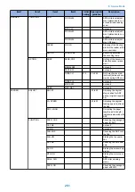
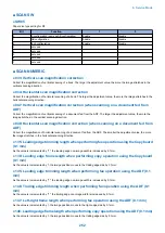


Item1
Item2
Item3
Item4
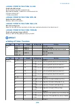
Initial
setting
Appropriate
guideline
Description
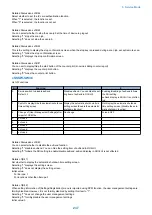
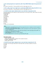
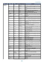
READER
FUNCTION
CCD
DF-WLVL2
ADF white level adjust-
ment (platen board cov-
er scan/stream reading
scan)
MTF-CLC
not used
DF-WLVL3
ADF white level adjust-
ment (platen board cov-
er scan)
DF-WLVL4
ADF white level adjust-
ment (DF scan)
CLEAR
R-CON
Clearing of the backup
area for the reader in the
main controller.
MISC-R
SCANLAMP
Executing activation of
the scanning lamp
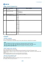
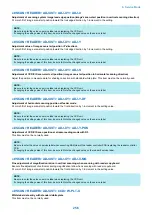
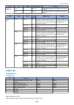
OPTION
BODY
SENS-CNF
Setting of the document
detection sensor place-
ment
MODELSZ2
not used
SZDT-SW
not used
DFDST-L1
215
0 to 255
Dirt detection level ad-
justment (between docu-
ments) during ADF use
DFDST-L2
not used
KSIZE-SW
not used
USER
SIZE-DET
not used
FEEDER
ADJUST
DOCST
-50 to 50
Adjusting the original
stop position for ADF
pickup (original tray pick-
up)
LA- SPEED
-30 to 30
Adjusting the original
feeding speed in stream
reading
DOC- LNGH
Correcting the paper
length in extra length/
indeterminate mode with
ADF
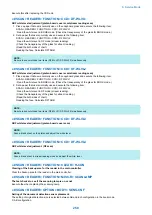
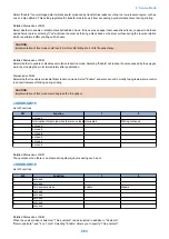
FUNCTION
FEED- CHK
Checking the passage of
paper for ADF
CL-CHK
not used
CL-ON
not used
FAN-CHK
Checking the ADF cool-
ing fan
FAN-ON
Starting the fan opera-
tion
SL-CHK
Checking the ADF sole-
noid
SL-ON
Starting the solenoid op-
eration
MTR-ON
Starting the motor oper-
ation
ROLL- CLN
ADF roller cleaning
mode
FEED- ON
Checking the passage of
paper with ADF
8. Service Mode
251
Summary of Contents for imageRUNNER 2525 Series
Page 1: ...Revision 9 0 imageRUNNER 2530 2525 2520 Series Service Manual ...
Page 62: ...No Part name 3 Laser unit 2 Technical Explanation 52 ...
Page 119: ...Periodical Service 3 Consumable Parts and Cleaning Parts 110 Cleaning Parts 115 ...
Page 125: ...Cleaning Parts Fixing guide Transfer guide 3 Periodical Service 115 ...
Page 136: ...List of Sensors S18 S17 S16 TS2 HU1 S9 S8 S19 TS1 S11 S12 4 Disassembly Assembly 126 ...
Page 165: ...5 Remove the idler gear 1 claw 1x 4 Disassembly Assembly 155 ...
Page 172: ... 1 4 2 3 2 2 Remove the scanner motor 4 screws 4x 4 Disassembly Assembly 162 ...
Page 186: ...3 Remove the RAM PCB Release the hook 4 Disassembly Assembly 176 ...
Page 187: ...Adjustment 5 Overview 178 Basic Adjustment 180 Adjustment when Replacing the Parts 182 ...
Page 209: ...Error Jam Alarm 7 Outline 200 Error Code 201 Jam Code 213 Alarm Code 219 ...
Page 231: ...Service Mode 8 Overview 222 Details of Service Mode 225 Remote UI Service Mode 302 ...
Page 314: ...Example of report display 8 Service Mode 304 ...
Page 387: ...APPENDICES Service Tools 378 General Circuit Diagram 379 ...