

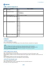


200s: copy
300s: print
400s: copy + print
500s: scan
700s: received file print
800s: report pint
900s: transmitted scan
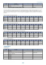
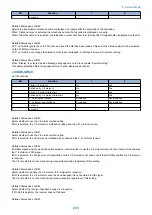
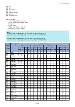
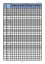
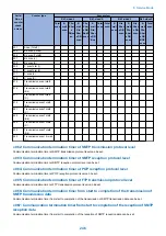
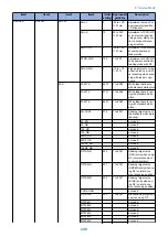
Guide to the Table
• 1: Count sheets of all sizes by one.
• 2: Count sheets of the large size by two.
• C: full color
• Bk: black mono
• L: large size (larger than A4/LTR)
• S: small size (A4/LTR or smaller)
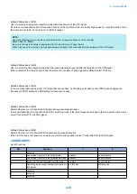
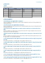
NOTE:
To make a change so that B4 papers (for print) will be counted as large-size, use
service mode: make the following selections, and change bit 0 to '1': #SSSW>SW33.
To make a change so that B4 papers (for scan) will be counted as large-size, use
service mode: make the following selections, and change bit 2 to '1': #SSSW>SW33.
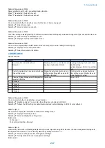
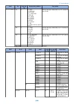
Serial
No. on
counter
check
screen
Counter type
Print system
Bk 1-sided L
Bk 1-sided S
Bk 2-sided L
Bk 2-sided S
Local
copy
PDL
FAX
Re-
port
Local
copy
PDL
FAX
Re-
port
Local
copy
PDL
FAX
Re-
port
Local
copy
PDL
FAX
Re-
port
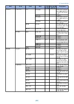
101
Total1
1
1
1
1
1
1
1
1
102
Total2
2
2
2
2
1
1
1
1
103
Total (L)
1
1
1
1
104
Total (S)
1
1
1
1
108
Total (Bk1)
1
1
1
1
1
1
1
1
109
Total (Bk2)
2
2
2
2
1
1
1
1
112
Total (Bk/L)
1
1
1
1
113
Total (Bk/S)
1
1
1
1
114
Total1 (2-si-
ded)
1
1
1
1
1
1
1
1
115
Total2 (2-si-
ded)
2
2
2
2
1
1
1
1
116
L (2-sided)
1
1
1
1
117
S (2-sided)
1
1
1
1
126
TotalA1
1
1
1
1
1
1
127
TotalA2
2
2
2
1
1
1
128
TotalA (L)
1
1
1
129
TotalA (S)
1
1
1
132
TotalA (Bk1)
1
1
1
1
1
1
133
TotalA (Bk2)
2
2
2
1
1
1
136
TotalA (Bk/L)
1
1
1
137
TotalA (Bk/S)
1
1
1
138
TotalA1 (2-si-
ded)
1
1
1
1
1
1
139
TotalA2 (2-si-
ded)
2
2
2
1
1
1
140
L A (2-sided)
1
1
1
141
S A (2-sided)
1
1
1
150
TotalB1
1
1
1
1
1
1
8. Service Mode
242
Summary of Contents for imageRUNNER 2525 Series
Page 1: ...Revision 9 0 imageRUNNER 2530 2525 2520 Series Service Manual ...
Page 62: ...No Part name 3 Laser unit 2 Technical Explanation 52 ...
Page 119: ...Periodical Service 3 Consumable Parts and Cleaning Parts 110 Cleaning Parts 115 ...
Page 125: ...Cleaning Parts Fixing guide Transfer guide 3 Periodical Service 115 ...
Page 136: ...List of Sensors S18 S17 S16 TS2 HU1 S9 S8 S19 TS1 S11 S12 4 Disassembly Assembly 126 ...
Page 165: ...5 Remove the idler gear 1 claw 1x 4 Disassembly Assembly 155 ...
Page 172: ... 1 4 2 3 2 2 Remove the scanner motor 4 screws 4x 4 Disassembly Assembly 162 ...
Page 186: ...3 Remove the RAM PCB Release the hook 4 Disassembly Assembly 176 ...
Page 187: ...Adjustment 5 Overview 178 Basic Adjustment 180 Adjustment when Replacing the Parts 182 ...
Page 209: ...Error Jam Alarm 7 Outline 200 Error Code 201 Jam Code 213 Alarm Code 219 ...
Page 231: ...Service Mode 8 Overview 222 Details of Service Mode 225 Remote UI Service Mode 302 ...
Page 314: ...Example of report display 8 Service Mode 304 ...
Page 387: ...APPENDICES Service Tools 378 General Circuit Diagram 379 ...