


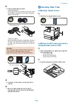
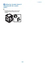


2. Press the button on the right cover to open the right
cover.
CAUTION:
To prevent the drum unit from being damaged, keep
the right cover open at least 5 cm during the installation
procedure.
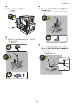
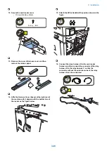
3. Turn the lock lever as shown below to release the
collected toner container. And then take out the
collected toner container.
4. Remove one screw from the developer pressure
lever. The screw does not exist in some machine
versions by destination.
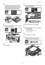
5. Turn the lever as shown below to release the drum
unit.
1x
6. Remove the drum cover. (Keep the drum cover
because it may be used later for machine relocation.)
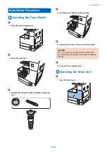
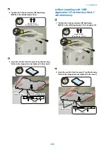
7. Unpack the new drum unit, remove packaging
materials, and then pull two orange rings to remove
the protective cover
CAUTION:
• Do not touch the drum surface while at work.
• Do not expose the drum surface to light for a long
period of time.
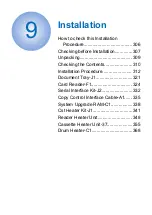
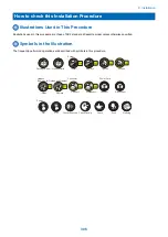
9. Installation
313
Summary of Contents for imageRUNNER 2525 Series
Page 1: ...Revision 9 0 imageRUNNER 2530 2525 2520 Series Service Manual ...
Page 62: ...No Part name 3 Laser unit 2 Technical Explanation 52 ...
Page 119: ...Periodical Service 3 Consumable Parts and Cleaning Parts 110 Cleaning Parts 115 ...
Page 125: ...Cleaning Parts Fixing guide Transfer guide 3 Periodical Service 115 ...
Page 136: ...List of Sensors S18 S17 S16 TS2 HU1 S9 S8 S19 TS1 S11 S12 4 Disassembly Assembly 126 ...
Page 165: ...5 Remove the idler gear 1 claw 1x 4 Disassembly Assembly 155 ...
Page 172: ... 1 4 2 3 2 2 Remove the scanner motor 4 screws 4x 4 Disassembly Assembly 162 ...
Page 186: ...3 Remove the RAM PCB Release the hook 4 Disassembly Assembly 176 ...
Page 187: ...Adjustment 5 Overview 178 Basic Adjustment 180 Adjustment when Replacing the Parts 182 ...
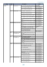
Page 209: ...Error Jam Alarm 7 Outline 200 Error Code 201 Jam Code 213 Alarm Code 219 ...
Page 231: ...Service Mode 8 Overview 222 Details of Service Mode 225 Remote UI Service Mode 302 ...
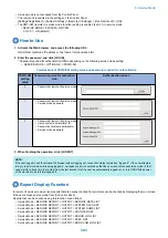
Page 314: ...Example of report display 8 Service Mode 304 ...
Page 387: ...APPENDICES Service Tools 378 General Circuit Diagram 379 ...