
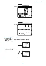


Target of delivery
Print mode
Single-sided/Doublesided
(2nd side)
Double-sided (1st side)
Count-up timing
Host machine
1st delivery tray
No.1 delivery sensor (S12)
Duplex feed sensor (S7)
2nd delivery tray
No. 2 delivery sensor (S42)
Inner finisher
Inner finisher inlet sensor (S1)
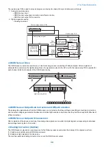
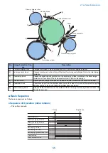
■ Fan
● Overview
Fan layout
FAN6
FAN3
FAN4
No.
Name
Function
Error code
FAN3
Exhaust fan (rear)
Cools the fixing unit.
E805-0000
E805-0001
FAN4
Exhaust fan (front)
Cools the fixing unit.
E805-0002
E805-0003
FAN6
Power supply cooling fan
Cools the power supply.
E804-0000
E804-0001
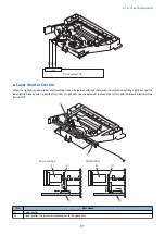
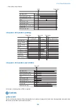
PTINT
LSTR
STBY
STBY
WUP
INI
*1
60sec
Exhaust fan (rear)
(FAN3)
Exhaust fan (front)
(FAN4)
Power supply cooling fan
(FAN6)N6)
:Full-speed
: 1/2-speed
*1: The fan operates at 1/2 speed only when the machine enters the standby mode after running for more than 8 minutes for
fixing.
2. Technical Explanation
43
Summary of Contents for imageRUNNER 2525 Series
Page 1: ...Revision 9 0 imageRUNNER 2530 2525 2520 Series Service Manual ...
Page 62: ...No Part name 3 Laser unit 2 Technical Explanation 52 ...
Page 119: ...Periodical Service 3 Consumable Parts and Cleaning Parts 110 Cleaning Parts 115 ...
Page 125: ...Cleaning Parts Fixing guide Transfer guide 3 Periodical Service 115 ...
Page 136: ...List of Sensors S18 S17 S16 TS2 HU1 S9 S8 S19 TS1 S11 S12 4 Disassembly Assembly 126 ...
Page 165: ...5 Remove the idler gear 1 claw 1x 4 Disassembly Assembly 155 ...
Page 172: ... 1 4 2 3 2 2 Remove the scanner motor 4 screws 4x 4 Disassembly Assembly 162 ...
Page 186: ...3 Remove the RAM PCB Release the hook 4 Disassembly Assembly 176 ...
Page 187: ...Adjustment 5 Overview 178 Basic Adjustment 180 Adjustment when Replacing the Parts 182 ...
Page 209: ...Error Jam Alarm 7 Outline 200 Error Code 201 Jam Code 213 Alarm Code 219 ...
Page 231: ...Service Mode 8 Overview 222 Details of Service Mode 225 Remote UI Service Mode 302 ...
Page 314: ...Example of report display 8 Service Mode 304 ...
Page 387: ...APPENDICES Service Tools 378 General Circuit Diagram 379 ...