


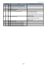

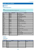
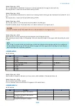


ACC ID
Jam Code
Type
Sensor Name
Sensor
ID
4
0003
Delay jam
Registration sensor
PI8
4
0004
Stationary jam
Registration sensor
PI8
4
0005
Delay jam
Read sensor
PI7
4
0006
Stationary jam
Read sensor
PI7
4
0007
Delay jam
Delivery reversal sensor
PI6
4
0008
Stationary jam
Delivery reversal sensor
PI6
4
0044
Stationary jam (first document)
Registration sensor
PI8
4
0045
Delay jam (first document)
Read sensor
PI7
4
0046
Stationary jam (first document)
Read sensor
PI7
4
0047
Delay jam (first document)
Delivery reversal sensor
PI6
4
0048
Stationary jam (first document)
Delivery reversal sensor
PI6
4
0071
Timing error
-
-
4
0090
ADF open jam
Copyboard cover open/closed Sen-
sor 0
S21
4
0091
User ADF open jam
Copyboard cover open/closed Sen-
sor 0
S21
4
0092
ADF cover open jam
Cover open/closed sensor
PI10
4
0093
User cover open jam
Cover open/closed sensor
PI10
4
0094
Initial stationary jam
Registration sensor or Read sensor
or Delivery reversal sensor
PI6, PI7,
PI8
4
0095
Pickup NG
Document set sensor
PI11
Inner Finisher-B1
S6
S16
S15
S22
S2
S1
S18
S19
S20
S11
S12
S9
S13
S10
S7
7. Error/Jam/Alarm
217
Summary of Contents for imageRUNNER 2525 Series
Page 1: ...Revision 9 0 imageRUNNER 2530 2525 2520 Series Service Manual ...
Page 62: ...No Part name 3 Laser unit 2 Technical Explanation 52 ...
Page 119: ...Periodical Service 3 Consumable Parts and Cleaning Parts 110 Cleaning Parts 115 ...
Page 125: ...Cleaning Parts Fixing guide Transfer guide 3 Periodical Service 115 ...
Page 136: ...List of Sensors S18 S17 S16 TS2 HU1 S9 S8 S19 TS1 S11 S12 4 Disassembly Assembly 126 ...
Page 165: ...5 Remove the idler gear 1 claw 1x 4 Disassembly Assembly 155 ...
Page 172: ... 1 4 2 3 2 2 Remove the scanner motor 4 screws 4x 4 Disassembly Assembly 162 ...
Page 186: ...3 Remove the RAM PCB Release the hook 4 Disassembly Assembly 176 ...
Page 187: ...Adjustment 5 Overview 178 Basic Adjustment 180 Adjustment when Replacing the Parts 182 ...
Page 209: ...Error Jam Alarm 7 Outline 200 Error Code 201 Jam Code 213 Alarm Code 219 ...
Page 231: ...Service Mode 8 Overview 222 Details of Service Mode 225 Remote UI Service Mode 302 ...
Page 314: ...Example of report display 8 Service Mode 304 ...
Page 387: ...APPENDICES Service Tools 378 General Circuit Diagram 379 ...