


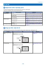


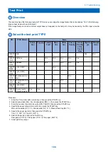


Basic Adjustment
Image position adjustment
Copy 10 sheets from each pickup position to check that the image margin and non-image area is within the standard.
• Each cassette
• Pickup tray
If it is not within the standard, go through the following procedures to adjust it.
CAUTION:
If changing the value of service mode item in this adjustment, enter the changed value in the service label.
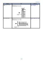
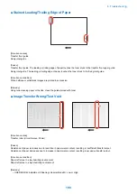
■ Margin Along the Leading Edge
Service mode> PRINT> PRINT NUMERIC> 053
An increase of '1' will increase the margin by 0.1 mm.
<range>
0 to 9999 (default: 25)
image
L1
Feeding direction
of paper
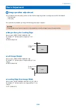
■ Left Image Margin
Service mode> PRINT> PRINT NUMERIC> 056
An increase of '1' will increase the margin width by 0.1 mm.
<range>
0 to 9999 (default: 25)
Feeding direction
of paper
L
1
image
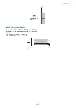
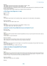
■ Leading Edge Non-Image Width
Service mode> SCAN> READER> ADJUST> ADJ-XY> ADJ-X
An increase of '1' will increase the non-image width by 0.1 mm.
<range>
1 to 211 (default: 20)
5. Adjustment
180
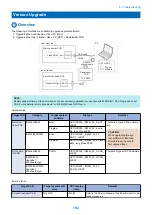
Summary of Contents for imageRUNNER 2525 Series
Page 1: ...Revision 9 0 imageRUNNER 2530 2525 2520 Series Service Manual ...
Page 62: ...No Part name 3 Laser unit 2 Technical Explanation 52 ...
Page 119: ...Periodical Service 3 Consumable Parts and Cleaning Parts 110 Cleaning Parts 115 ...
Page 125: ...Cleaning Parts Fixing guide Transfer guide 3 Periodical Service 115 ...
Page 136: ...List of Sensors S18 S17 S16 TS2 HU1 S9 S8 S19 TS1 S11 S12 4 Disassembly Assembly 126 ...
Page 165: ...5 Remove the idler gear 1 claw 1x 4 Disassembly Assembly 155 ...
Page 172: ... 1 4 2 3 2 2 Remove the scanner motor 4 screws 4x 4 Disassembly Assembly 162 ...
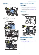
Page 186: ...3 Remove the RAM PCB Release the hook 4 Disassembly Assembly 176 ...
Page 187: ...Adjustment 5 Overview 178 Basic Adjustment 180 Adjustment when Replacing the Parts 182 ...
Page 209: ...Error Jam Alarm 7 Outline 200 Error Code 201 Jam Code 213 Alarm Code 219 ...
Page 231: ...Service Mode 8 Overview 222 Details of Service Mode 225 Remote UI Service Mode 302 ...
Page 314: ...Example of report display 8 Service Mode 304 ...
Page 387: ...APPENDICES Service Tools 378 General Circuit Diagram 379 ...