


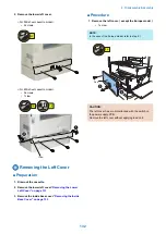
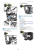

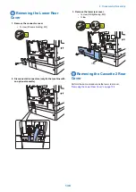

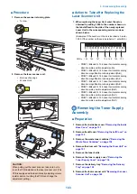

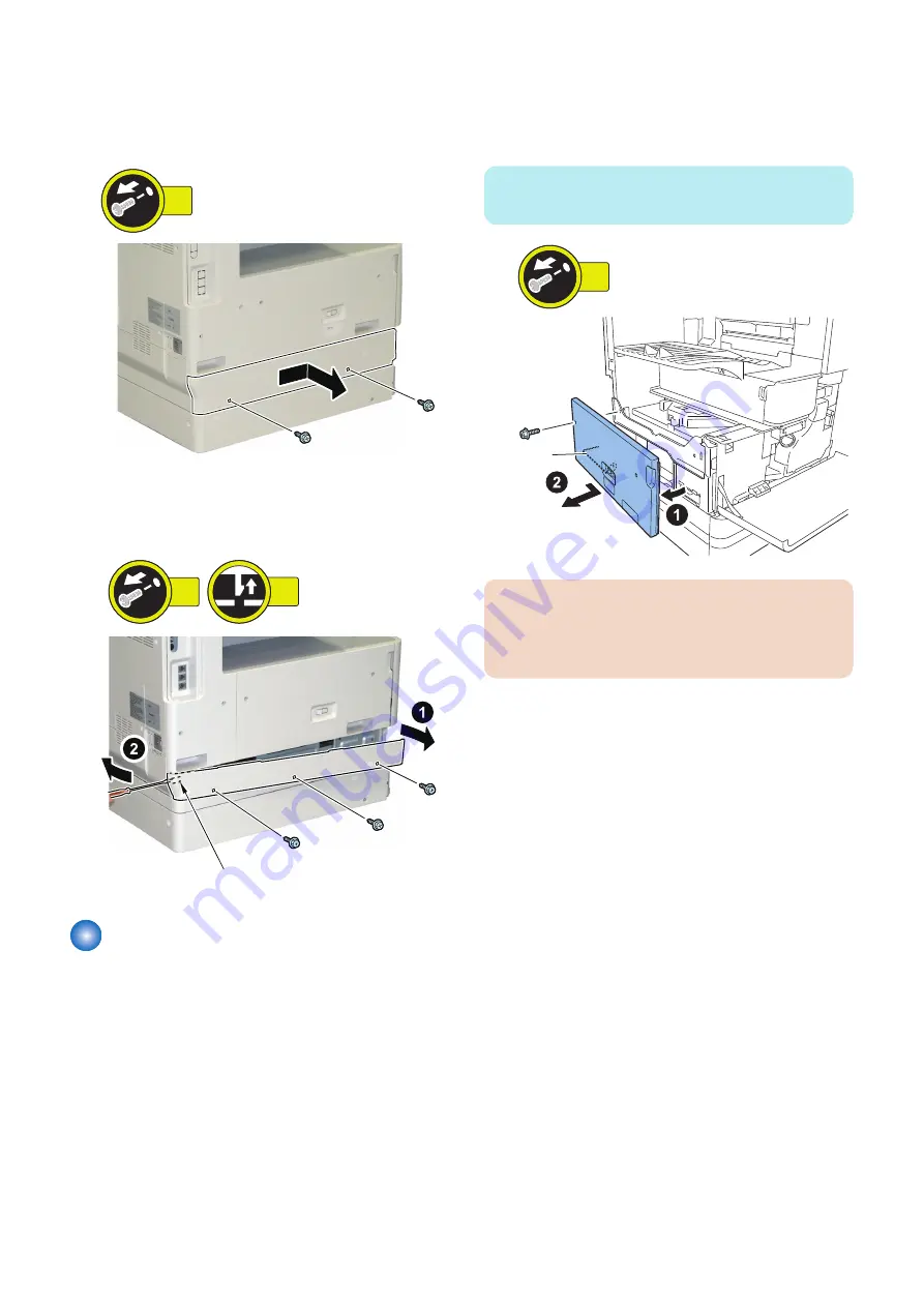
2. Remove the lower left cover.
<For 550-sheet cassette model>
• 2 screws
2x
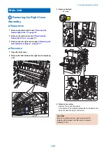
<For 250-sheet cassette model>
• 3 screws
• 1 claw
3x
1x
Claw
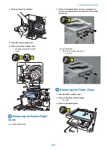
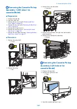
Removing the Left Cover
■ Preparation
1. Draw out the cassette.
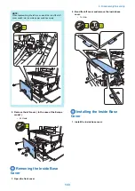
2. Remove the lower left cover.
3. Remove the inside base cover.
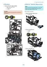
■ Procedure
1. Remove the left cover. ( except the Europe model )
• 1 screw
NOTE:
In the case of the Europe model, refer to step 2.).
1x
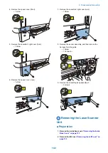
Rod
CAUTION:
The left cover has a rod interlocked with the switch on
the power supply PCB.
Remove the left cover without applying load on it.
4. Disassembly/Assembly
132
Summary of Contents for imageRUNNER 2525 Series
Page 1: ...Revision 9 0 imageRUNNER 2530 2525 2520 Series Service Manual ...
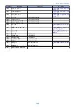
Page 62: ...No Part name 3 Laser unit 2 Technical Explanation 52 ...
Page 119: ...Periodical Service 3 Consumable Parts and Cleaning Parts 110 Cleaning Parts 115 ...
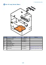
Page 125: ...Cleaning Parts Fixing guide Transfer guide 3 Periodical Service 115 ...
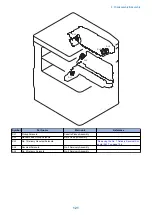
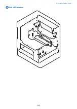
Page 136: ...List of Sensors S18 S17 S16 TS2 HU1 S9 S8 S19 TS1 S11 S12 4 Disassembly Assembly 126 ...
Page 165: ...5 Remove the idler gear 1 claw 1x 4 Disassembly Assembly 155 ...
Page 172: ... 1 4 2 3 2 2 Remove the scanner motor 4 screws 4x 4 Disassembly Assembly 162 ...
Page 186: ...3 Remove the RAM PCB Release the hook 4 Disassembly Assembly 176 ...
Page 187: ...Adjustment 5 Overview 178 Basic Adjustment 180 Adjustment when Replacing the Parts 182 ...
Page 209: ...Error Jam Alarm 7 Outline 200 Error Code 201 Jam Code 213 Alarm Code 219 ...
Page 231: ...Service Mode 8 Overview 222 Details of Service Mode 225 Remote UI Service Mode 302 ...
Page 314: ...Example of report display 8 Service Mode 304 ...
Page 387: ...APPENDICES Service Tools 378 General Circuit Diagram 379 ...