


Service Tools
Special Tools
Tool name
Tool No. Rank (*)
Shape
Uses
Digital multimeter
FY9-2002
A
For making electrical checks.
Tester extension pin
FY9-3038
A
As an addition when making an electrical check.
Tester extension pin
(L-shipped)
FY9-3039
A
As an addition when making an electrical check.
NA-3 Test Chart
FY9-9196
A
For checking and adjusting images.
Mirror cleaning tool
FL2-9842
--
Used for cleaning the mirror in the CCD unit.
This part is installed in the reader unit.
(Not a service tool)
*
A: each service engineer is expected to carry one.
B: each group of 5 service engineers is expected to carry one.
C: each workshop is expected to carry one.
Oils and Solvents
Name
Uses
Composition
Remarks
Alcohol
cleaning;
e.g.,
glass, plastic, rubber;
external covers
fluoride-family
hydrocarbon
alcohol
surface activating agent water
Do not bring near fire.
Procure locally.
IPA (isopropyl alcohol) may be
substituted.
Lubricant
scanner rail
stream reading glass
silicone oil
KF96SS (300CS)
FY9-6011 (50 cc)
Service Tools
378
Summary of Contents for imageRUNNER 2525 Series
Page 1: ...Revision 9 0 imageRUNNER 2530 2525 2520 Series Service Manual ...
Page 62: ...No Part name 3 Laser unit 2 Technical Explanation 52 ...
Page 119: ...Periodical Service 3 Consumable Parts and Cleaning Parts 110 Cleaning Parts 115 ...
Page 125: ...Cleaning Parts Fixing guide Transfer guide 3 Periodical Service 115 ...
Page 136: ...List of Sensors S18 S17 S16 TS2 HU1 S9 S8 S19 TS1 S11 S12 4 Disassembly Assembly 126 ...
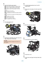
Page 165: ...5 Remove the idler gear 1 claw 1x 4 Disassembly Assembly 155 ...
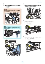
Page 172: ... 1 4 2 3 2 2 Remove the scanner motor 4 screws 4x 4 Disassembly Assembly 162 ...
Page 186: ...3 Remove the RAM PCB Release the hook 4 Disassembly Assembly 176 ...
Page 187: ...Adjustment 5 Overview 178 Basic Adjustment 180 Adjustment when Replacing the Parts 182 ...
Page 209: ...Error Jam Alarm 7 Outline 200 Error Code 201 Jam Code 213 Alarm Code 219 ...
Page 231: ...Service Mode 8 Overview 222 Details of Service Mode 225 Remote UI Service Mode 302 ...
Page 314: ...Example of report display 8 Service Mode 304 ...
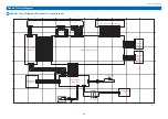
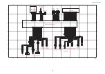
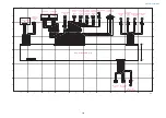
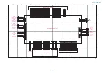
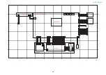
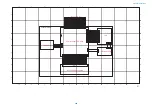
Page 387: ...APPENDICES Service Tools 378 General Circuit Diagram 379 ...