


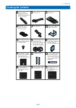


Unpacking
Unpacking the Machine and
Removing the Packaging
Materials
NOTE:
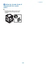
When installing a cassette pedestal, be sure to place the
machine on the cassette pedestal. (For the procedure for
installing the cassette pedestal, refer to the Cassette
Pedestal Installation Procedure.)
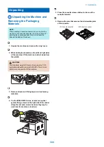
1. Unpack the machine and remove the vinyl cover.
2. While holding four handles on the left and right sides
of the machine, lift the machine to take it down from
the palette.
CAUTION:
The maximum weight of the machine is approx. 78.8
kg (double-cassette model with a DADF). Two or more
persons are required to lift the machine.
3. Remove all pieces of fixing tapes and cushioning
materials.
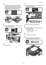
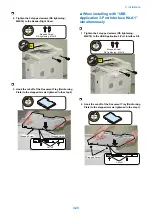
4. For the iR2545/2535 Series, remove two optical
system fixing screws on the right side of the reader.
(Keep the removed screws because they may be
used later for machine relocation.)
2x
5. Press the cassette release button to draw out the
cassette forward.
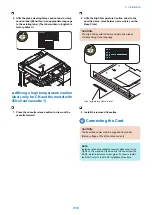
6. Remove the wire that secures the intermediate plate
of the cassette.
<250 sheets cassette>
<550 sheets cassette>
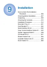
9. Installation
309
Summary of Contents for imageRUNNER 2525 Series
Page 1: ...Revision 9 0 imageRUNNER 2530 2525 2520 Series Service Manual ...
Page 62: ...No Part name 3 Laser unit 2 Technical Explanation 52 ...
Page 119: ...Periodical Service 3 Consumable Parts and Cleaning Parts 110 Cleaning Parts 115 ...
Page 125: ...Cleaning Parts Fixing guide Transfer guide 3 Periodical Service 115 ...
Page 136: ...List of Sensors S18 S17 S16 TS2 HU1 S9 S8 S19 TS1 S11 S12 4 Disassembly Assembly 126 ...
Page 165: ...5 Remove the idler gear 1 claw 1x 4 Disassembly Assembly 155 ...
Page 172: ... 1 4 2 3 2 2 Remove the scanner motor 4 screws 4x 4 Disassembly Assembly 162 ...
Page 186: ...3 Remove the RAM PCB Release the hook 4 Disassembly Assembly 176 ...
Page 187: ...Adjustment 5 Overview 178 Basic Adjustment 180 Adjustment when Replacing the Parts 182 ...
Page 209: ...Error Jam Alarm 7 Outline 200 Error Code 201 Jam Code 213 Alarm Code 219 ...
Page 231: ...Service Mode 8 Overview 222 Details of Service Mode 225 Remote UI Service Mode 302 ...
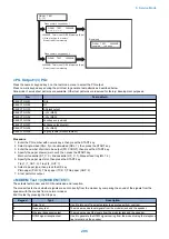
Page 314: ...Example of report display 8 Service Mode 304 ...
Page 387: ...APPENDICES Service Tools 378 General Circuit Diagram 379 ...