


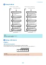


Using the Mode
#SSSW
# N U M E R I C
# N U M E R I C
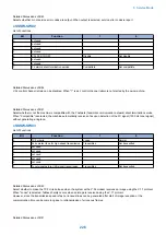
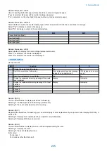
2) Selecting a Menu Item
Select the Menu item using the
[left arrow]/[right arrow] on the
touch panel.
3) Press [OK].
5) Registering/Setting Data
Enter data using the keypad,
and then press [OK].
6) Press the [Stop]/[Additional
functions]/[Reset] key to end
the service mode.
# N U M E R I C
# N U M E R I C
0 0 1
0 0 1
0 0 2
0 0 2
0
0
1 0
4) Selecting a Prarameter
Select the Prarameter using the
[left arrow]/[right arrow].
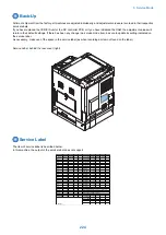
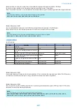
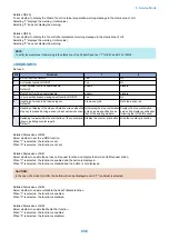
1) Selecting Service Mode
# S S S W
3) Selecting a Menu Item
Press [OK].
2) Press [OK] on the
touch panel.
5) Registering/Setting Data
Enter data using the keypad,
and press the [OK].
6) Press the [Stop]/[Additional
functions]/[Reset] key to end
the service mode.
0 3 3
4) Selecting a Bit Switch
Select the bit using the
[left arrow]/[right arrow] on
the touch panel.
# S S S W
# S S S W
000000000
000000000
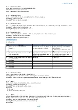
<Operation at the time of Bit SW>
<Operation at the time of Parameter>
0 3 3
# S S S W
000000000
0 3 3
# S S S W
000000001
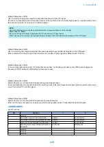
1) Selecting Service Mode
NOTE:
Push the (*) key when inputting the minus(-).
Therefore, (+) and (-) is changed.
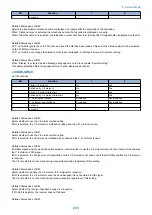
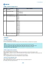
Setting of Bit Switch
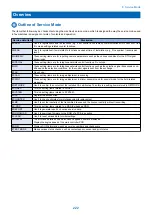
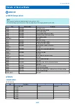
■ Outline
● Bit Switch Composition
The items registered and set by each of these switches comprise 8-bit switches.
The figure below shows which numbers are assigned to which bits. Each bit has a value of either 0 or 1.
001
#SSSW
0
0
0
0
0
0
0
0
Bi
t
7
Bi
t
6
Bi
t
5
Bi
t
4
Bi
t
3
Bi
t
2
Bi
t
1
Bi
t
0
CAUTION:
Do not change service data identified as "not used"; they are set as initial settings.
8. Service Mode
223
Summary of Contents for imageRUNNER 2525 Series
Page 1: ...Revision 9 0 imageRUNNER 2530 2525 2520 Series Service Manual ...
Page 62: ...No Part name 3 Laser unit 2 Technical Explanation 52 ...
Page 119: ...Periodical Service 3 Consumable Parts and Cleaning Parts 110 Cleaning Parts 115 ...
Page 125: ...Cleaning Parts Fixing guide Transfer guide 3 Periodical Service 115 ...
Page 136: ...List of Sensors S18 S17 S16 TS2 HU1 S9 S8 S19 TS1 S11 S12 4 Disassembly Assembly 126 ...
Page 165: ...5 Remove the idler gear 1 claw 1x 4 Disassembly Assembly 155 ...
Page 172: ... 1 4 2 3 2 2 Remove the scanner motor 4 screws 4x 4 Disassembly Assembly 162 ...
Page 186: ...3 Remove the RAM PCB Release the hook 4 Disassembly Assembly 176 ...
Page 187: ...Adjustment 5 Overview 178 Basic Adjustment 180 Adjustment when Replacing the Parts 182 ...
Page 209: ...Error Jam Alarm 7 Outline 200 Error Code 201 Jam Code 213 Alarm Code 219 ...
Page 231: ...Service Mode 8 Overview 222 Details of Service Mode 225 Remote UI Service Mode 302 ...
Page 314: ...Example of report display 8 Service Mode 304 ...
Page 387: ...APPENDICES Service Tools 378 General Circuit Diagram 379 ...