

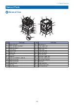


• Copyboard cover open/closed sensor (front: S32/rear: S33) detection signal
Detects the open/close status of the copyboard cover
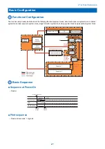
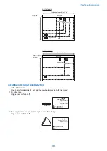
● Scanner Motor Control
Scanner motor driver turns on/off the motor and controls its direction/speed of rotation according to the signals from CPU.
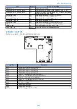
Reader relay PCB
5V
+24V
RTP3APWN
RTP3BPWN
RTP3A
RTP3B
MO_ACTIVE
+5V
J559
B*
B
A
A*
IC2
Motor
driver
1
2
3
4
M31
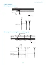
NOTE:
The scan speed of this machine is as follows:
Copy (100%): 123 mm/sec
Color send (300 dpi x 300 dpi): 123 mm/sec or 61.5 mm/sec
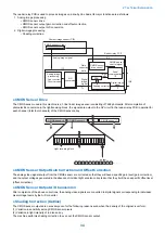
1. Forward Movement during Image Scan
During image scan, operation of the contact image sensor (CIS) is controlled by controlling the motor as shown below.
Start position
position
Acceleration
Original
leading edge
Normal speed
Original
trailing edge
Deceleration
Stop
Shift
speed
Shift distance
[1]
[2]
[3]
[4]
[1] Acceleration area: Accelerates until a speed suited to the selected mode is reached
[2] Run-up speed area: Run-up margin to ensure a stable speed.
[3] Image reading area: Reads an image at a specific speed.
[4] Deceleration area: Decelerates and stops promptly once the image end is reached.
2. Backward Movement after Image Scan
After image scan, the carriage moves back to the contact image sensor (CIS) shading position at the constant speed (123
mm/sec).
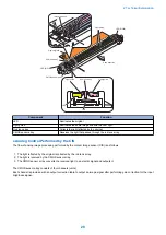
■ Contact Image Sensor (CIS)
● Outline
The original is exposed to light and read using the contact image sensor (CIS) to read the image on a line-by-line basis.
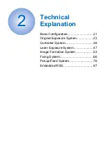
2. Technical Explanation
27
Summary of Contents for imageRUNNER 2525 Series
Page 1: ...Revision 9 0 imageRUNNER 2530 2525 2520 Series Service Manual ...
Page 62: ...No Part name 3 Laser unit 2 Technical Explanation 52 ...
Page 119: ...Periodical Service 3 Consumable Parts and Cleaning Parts 110 Cleaning Parts 115 ...
Page 125: ...Cleaning Parts Fixing guide Transfer guide 3 Periodical Service 115 ...
Page 136: ...List of Sensors S18 S17 S16 TS2 HU1 S9 S8 S19 TS1 S11 S12 4 Disassembly Assembly 126 ...
Page 165: ...5 Remove the idler gear 1 claw 1x 4 Disassembly Assembly 155 ...
Page 172: ... 1 4 2 3 2 2 Remove the scanner motor 4 screws 4x 4 Disassembly Assembly 162 ...
Page 186: ...3 Remove the RAM PCB Release the hook 4 Disassembly Assembly 176 ...
Page 187: ...Adjustment 5 Overview 178 Basic Adjustment 180 Adjustment when Replacing the Parts 182 ...
Page 209: ...Error Jam Alarm 7 Outline 200 Error Code 201 Jam Code 213 Alarm Code 219 ...
Page 231: ...Service Mode 8 Overview 222 Details of Service Mode 225 Remote UI Service Mode 302 ...
Page 314: ...Example of report display 8 Service Mode 304 ...
Page 387: ...APPENDICES Service Tools 378 General Circuit Diagram 379 ...