


Group
Item
Description
Detail
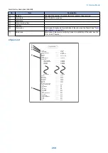
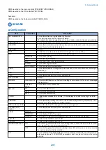
(2) SENS/ SW
CHECK
ADF
ADF sensor check
L2: Document length sensor 2
0/Document presence
1/Document absenc
LT: Last document detection sensor
0/Document presence
1/Document absenc
EX: Delivery reversal sensor
0/Document presence
1/Document absenc
DR: Read sensor
0/Document presence
1/Document absenc
RG: Registration paper sensor
0/Document presence
1/Document absenc
CV: Cover open/close sensor
0/Cover closed
1/Cover open
DS: Document set snsor
0/Document presence
1/Document absenc
RK: Release motor HP sensor
0/besides HP
1/HP
TM: Timing sensor
0/Document presence
1/Document absenc
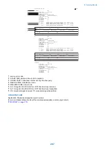
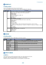
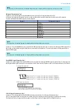
Card reader test <6-3: NCR sts>
Press numeric keypad key 3 on the FACULTY menu to select the card reader test.
In this test, verify the successful operations of the card reader.
NCR Sts: 12345678
DPT MGN OK RDY 1234
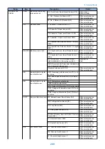
[1] Card reader and card availability indication
Card available: Eight-digit card ID
No card: Card None
No card reader available: NCR None
[2] Card type and card reader status indication
DPT: Department card
PRC: Unit pricing card
MAX: Upper limit setting card
ERS: Erased card
SRV: Service card
(No indication): No card
[3] Card type
MGN: Magnetic card
OPT: Optical card
[1]
[2]
[3] [4]
[5]
[6]
Press numeric keypad key 3
[4] Can status
OK: Normal scan
ERR: Scan error
NG: Nonstandard error
(No indication): No card
[5] Equipment status
IN: Initialization in progress
RDY: Ready
[6] Card reader version indication
Four-digit number
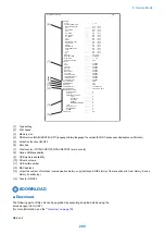
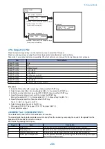
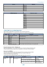
Line signal reception test <6-9: LINE DETECT>
Press numeric keypad key 9 on the FACULTY menu to select the line signal reception test.
In this test, verify the successful operations of the NCU signal sensor and the frequency counter.
Menu 1 detects the CI state, while menu 3 detects the CNG signal.
Test menu 1
8. Service Mode
300
Summary of Contents for imageRUNNER 2525 Series
Page 1: ...Revision 9 0 imageRUNNER 2530 2525 2520 Series Service Manual ...
Page 62: ...No Part name 3 Laser unit 2 Technical Explanation 52 ...
Page 119: ...Periodical Service 3 Consumable Parts and Cleaning Parts 110 Cleaning Parts 115 ...
Page 125: ...Cleaning Parts Fixing guide Transfer guide 3 Periodical Service 115 ...
Page 136: ...List of Sensors S18 S17 S16 TS2 HU1 S9 S8 S19 TS1 S11 S12 4 Disassembly Assembly 126 ...
Page 165: ...5 Remove the idler gear 1 claw 1x 4 Disassembly Assembly 155 ...
Page 172: ... 1 4 2 3 2 2 Remove the scanner motor 4 screws 4x 4 Disassembly Assembly 162 ...
Page 186: ...3 Remove the RAM PCB Release the hook 4 Disassembly Assembly 176 ...
Page 187: ...Adjustment 5 Overview 178 Basic Adjustment 180 Adjustment when Replacing the Parts 182 ...
Page 209: ...Error Jam Alarm 7 Outline 200 Error Code 201 Jam Code 213 Alarm Code 219 ...
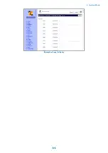
Page 231: ...Service Mode 8 Overview 222 Details of Service Mode 225 Remote UI Service Mode 302 ...
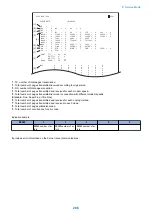
Page 314: ...Example of report display 8 Service Mode 304 ...
Page 387: ...APPENDICES Service Tools 378 General Circuit Diagram 379 ...