

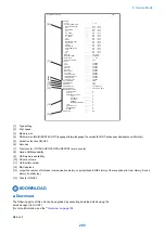


Keypad
Baud rate
0
3429baud
1
3200baud
2
3000baud
3
2800baud
4
2743baud
5
2400baud
Left/right arrow key
Transmission speed
<
>
2400bps
4800bps
7200bps
9600bps
12000bps
14400bps
16800bps
19200bps
21600bps
24000bps
26400bps
28800bps
31200bps
33600bps
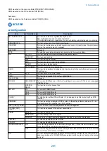
● FUNCTION Test <(6) FUNCTION TEST>
Press the numeric keypad key 6 on the test mode menu to select the function test.
Press numeric keypad keys 1 to 4 and 9 during the function test to enter the menus listed below.
Keypad
Type
Description
1
G3 signal transmission test
Transmits 4800-bps G3 signals to a telephone line and speaker
2
Sensor test
Sensor actuation test
3
Accessory
4
ADF test
ADF operation test
5
Not used
6
Not used
7
Not used
8
Not used
9
Line signal reception test
NCU board signal sensor and frequency counter operation test
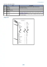
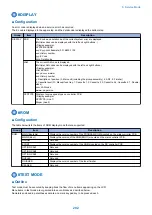
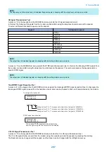
G3 signal transmission test (6-1: G3 480 bps Tx)
Press numeric keypad key 1 on the FUNCTION TEST menu to select the G3 signal transmission test.
This test transmits 4800-bps G3 signals from the telephone line connection terminal and speaker.
Sensor test (6-2: SENSOR)
This mode is used to verify the status of the unit sensors from the touch panel (LCD) indications.
Press numeric keypad key 3 on the FUNCTION TEST menu to select the sensor test.
To select a minor item, press the START key.
The touch panel (LCD) indications change as the associated sensors turn on and off.
Group
Item
Description
Detail
(2) SENS/ SW
CHECK
FLAG
Sensor check with flag
(manual check)
CT: Waste Toner Full Sensor(S17)
0/Full
1/Available
TC: Toner Cover Open/Closed Sensor (S16)
1/Cover open
0/Cover closed
MW: Manual Feeder Paper Size Sensor (S8)
0/Document presence
1/Document absenc
8. Service Mode
298
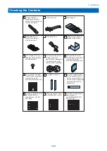
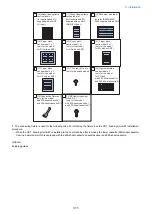
Summary of Contents for imageRUNNER 2525 Series
Page 1: ...Revision 9 0 imageRUNNER 2530 2525 2520 Series Service Manual ...
Page 62: ...No Part name 3 Laser unit 2 Technical Explanation 52 ...
Page 119: ...Periodical Service 3 Consumable Parts and Cleaning Parts 110 Cleaning Parts 115 ...
Page 125: ...Cleaning Parts Fixing guide Transfer guide 3 Periodical Service 115 ...
Page 136: ...List of Sensors S18 S17 S16 TS2 HU1 S9 S8 S19 TS1 S11 S12 4 Disassembly Assembly 126 ...
Page 165: ...5 Remove the idler gear 1 claw 1x 4 Disassembly Assembly 155 ...
Page 172: ... 1 4 2 3 2 2 Remove the scanner motor 4 screws 4x 4 Disassembly Assembly 162 ...
Page 186: ...3 Remove the RAM PCB Release the hook 4 Disassembly Assembly 176 ...
Page 187: ...Adjustment 5 Overview 178 Basic Adjustment 180 Adjustment when Replacing the Parts 182 ...
Page 209: ...Error Jam Alarm 7 Outline 200 Error Code 201 Jam Code 213 Alarm Code 219 ...
Page 231: ...Service Mode 8 Overview 222 Details of Service Mode 225 Remote UI Service Mode 302 ...
Page 314: ...Example of report display 8 Service Mode 304 ...
Page 387: ...APPENDICES Service Tools 378 General Circuit Diagram 379 ...