


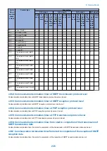


NOTE:
Any of the following error codes may be indicated because of the condition of the line ##0005, ##0018
The line condition identification time is between when the dial signal is transmitted and when the line condition is cut for the
transmitting party, while it is between when the DIS signal is transmitted and when the line is cut for the receiving party.
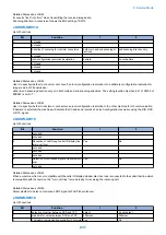
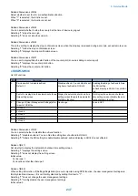
● 011: T.30 T1 timer (for reception)
Set the T1 timer for the receiver (wait time after DIS transmission starts until a significant signal is received).
● 012: The maximum number of received lines
The number of lines at reception can be limited.
● 013:T.30 EOL timer
Set it so that the 1-line transmission time is longer for reception to prevent reception errors
caused by a long data length per line (e.g., computer FAX).
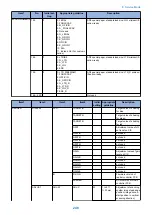
● 016: time length to first response at time of fax/tel switchover
Allows setting of the time from seizing the line till pseudo RBT is sent, when the Fax/ Tel switching function is operating.
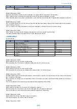
● 017:pseudo RBT signal pattern ON time length/018: pseudo RBT signal pattern OFF time
length (short)/019: pseudo RBT signal pattern OFF time length (long)
Use it to set the pseudo CI signal pattern transmitted at time of a fax/tel switchover.
017: pseudo RBT signal pattern ON time length/018: pseudo RBT signal pattern OFF time length (short)/019: pseudo RBT signal
pattern OFF time length (long)
● 020: pseudo CI signal pattern ON time length/021: pseudo CI signal pattern OFF time
length (short)/022: pseudo CI signal pattern OFF time length (long)
Use it to set the pseudo CI signal pattern transmitted at time of a fax/tel switchover.
● 023:CNG detention level for fax/tel switchover
Use it to set the CNG detention level for a fax/tel switchover.
● 024:pseudo RBT transmission level at time of fax/tel switchover
Use it to set the pseudo transmission level for a fax/tel switchover.
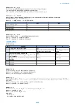
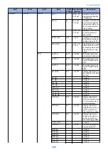
● 025: Answering machine connection function signal detection time
Sets the signal detection time for the answering machine connection function operation.
When the answering machine connection function is operating, if the function does not operate normally because the fax does
not detect CNG signal sent from the line, raise this parameter to increase the signal detection time.
● 027:V.21 low-speed flag preamble identification length
Use it to detect the time of detection after which command analysis is started after detecting V.21 low-speed command preambles
continuously for a specific period of time.
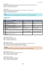
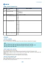
● 056 - 061: Count type select
Use it to confirm the count type indicated on the Counter Check screen, which appears in response to a press on the Counter
key.
When '0' is selected, count type will not be indicated.
056: Use it to indicate the type of software counter 1 of the control panel. The type of soft counter 1 cannot be changed.
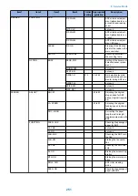
057: Use it to change the type of soft counter 2* of the control panel to suit the needs of the user.
058: Use it to change the type of soft counter 3* of the control panel to suit the needs of the user.
059: Use it to change the type of soft counter 4* of the control panel to suit the needs of the user.
060: Use it to change the type of soft counter 5* of the control panel to suit the needs of the user.
061: Use it to change the type of soft counter 6* of the control panel to suit the needs of the user.
*:The default type settings of soft counter is different from models.
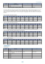
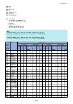
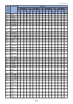
<Soft Counter Specifications>
The soft counters are classified a follows in terms of input numbers:
100s: total
8. Service Mode
241
Summary of Contents for imageRUNNER 2525 Series
Page 1: ...Revision 9 0 imageRUNNER 2530 2525 2520 Series Service Manual ...
Page 62: ...No Part name 3 Laser unit 2 Technical Explanation 52 ...
Page 119: ...Periodical Service 3 Consumable Parts and Cleaning Parts 110 Cleaning Parts 115 ...
Page 125: ...Cleaning Parts Fixing guide Transfer guide 3 Periodical Service 115 ...
Page 136: ...List of Sensors S18 S17 S16 TS2 HU1 S9 S8 S19 TS1 S11 S12 4 Disassembly Assembly 126 ...
Page 165: ...5 Remove the idler gear 1 claw 1x 4 Disassembly Assembly 155 ...
Page 172: ... 1 4 2 3 2 2 Remove the scanner motor 4 screws 4x 4 Disassembly Assembly 162 ...
Page 186: ...3 Remove the RAM PCB Release the hook 4 Disassembly Assembly 176 ...
Page 187: ...Adjustment 5 Overview 178 Basic Adjustment 180 Adjustment when Replacing the Parts 182 ...
Page 209: ...Error Jam Alarm 7 Outline 200 Error Code 201 Jam Code 213 Alarm Code 219 ...
Page 231: ...Service Mode 8 Overview 222 Details of Service Mode 225 Remote UI Service Mode 302 ...
Page 314: ...Example of report display 8 Service Mode 304 ...
Page 387: ...APPENDICES Service Tools 378 General Circuit Diagram 379 ...