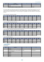


No.
Item
Range of settings
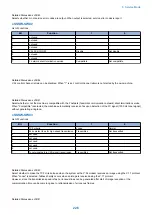
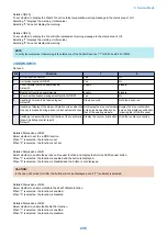
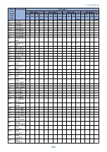
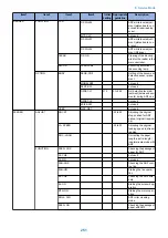
057
Display the type of soft counter 2
0 to 999
058
Display the type of soft counter 3
0 to 999
059
Display the type of soft counter 4
0 to 999
060
Display the type of soft counter 5
0 to 999
061
Display the type of soft counter 6
0 to 999
062
Communication termination timer at SMTP transmission protocol level 0 to 65535 sec
063
Communication termination timer at SMTP reception protocol level
0 to 65535 sec
064
Communication termination timer at POP reception protocol level
0 to 65535 sec
065
Communication termination timer at FTP transmission protocol level
0 to 65535 sec
066
Communication termination timer from start to completion of the trans-
mission of SMTP transmission data
0 to 65535 sec
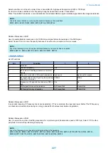
067
Communication termination timer from start to completion of the recep-
tion of SMTP reception data
0 to 65535 sec
068
Communication termination timer from start to completion of the recep-
tion of POP reception data
0 to 65535 sec
069
Communication termination timer from start to completion of the trans-
mission of FTP transmission data
0 to 65535 sec
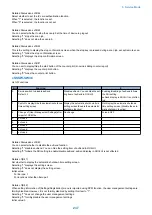
074
e-RDS RGW port number
1 to 65535 default: 443
075
Interval of transmission for e-RDS 3rd party
1 to 168 (hours) default: 24
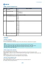
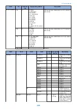
■ Details
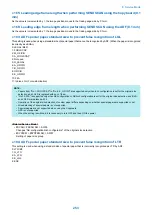
● <002:RTN transmission condition (1)><003: RTN transmission condition (2)><004: RTN
transmission condition (3)>
Use it to set RTN signal transmission conditions. Raise these parameters for more lenient conditions if errors occur frequently at
time of reception because of transmission of the RTN signal.
NOTE:
Any of the following error codes may be indicated at time of reception because of RTN signal transmission
##0104, ##0107, ##0114, ##0201
RTN signal transmission condition (1) affects the ratio of error lines to the total number of lines per single page of received images.
RTN signal transmission condition (2) affects the standard value (*2) of burst errors (*1).
RTN signal condition (3) affects the number of errors not reaching the standard value of burst errors.
*1: transmission error occurring cover several lines.
*2: for instance, if '15' is set, a single burst error will represent an error occurring continuously cover 15 lines.
If any of these lines is detected while an image signal is being received, the RTN signal will be transmitted after receiving the
protocol signal of the transmitting party. Higher parameters restrict the transmission of the RTN signal.
● 005:NCC pause length (pre-ID code)
Use it to set the length of the pause automatically entered between access code and ID code when the NCC (New Common
Carrier) line is used for dialing.
● 006:NCC pause length (post-ID code)
Use it to set the length of the pause automatically entered between ID code and telephone number of the other party when the
NCC (New Common Carrier) line is used for dialing.
● 008: Time from Right After Dialing by Auto-dialing to Start of Communication
The time to shift to transmission after automatic dialing can be set. The timing to start communication after connecting to the
other party is delayed by the specified period of time.
● 010: line connection identification length
Use it to set the time for identifying the line connection.
Raise this parameter if errors occur frequently at time of communication because of the condition of the line
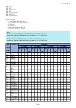
8. Service Mode
240
Summary of Contents for imageRUNNER 2525 Series
Page 1: ...Revision 9 0 imageRUNNER 2530 2525 2520 Series Service Manual ...
Page 62: ...No Part name 3 Laser unit 2 Technical Explanation 52 ...
Page 119: ...Periodical Service 3 Consumable Parts and Cleaning Parts 110 Cleaning Parts 115 ...
Page 125: ...Cleaning Parts Fixing guide Transfer guide 3 Periodical Service 115 ...
Page 136: ...List of Sensors S18 S17 S16 TS2 HU1 S9 S8 S19 TS1 S11 S12 4 Disassembly Assembly 126 ...
Page 165: ...5 Remove the idler gear 1 claw 1x 4 Disassembly Assembly 155 ...
Page 172: ... 1 4 2 3 2 2 Remove the scanner motor 4 screws 4x 4 Disassembly Assembly 162 ...
Page 186: ...3 Remove the RAM PCB Release the hook 4 Disassembly Assembly 176 ...
Page 187: ...Adjustment 5 Overview 178 Basic Adjustment 180 Adjustment when Replacing the Parts 182 ...
Page 209: ...Error Jam Alarm 7 Outline 200 Error Code 201 Jam Code 213 Alarm Code 219 ...
Page 231: ...Service Mode 8 Overview 222 Details of Service Mode 225 Remote UI Service Mode 302 ...
Page 314: ...Example of report display 8 Service Mode 304 ...
Page 387: ...APPENDICES Service Tools 378 General Circuit Diagram 379 ...