


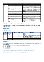


• Detailed Discussions of Bit 6
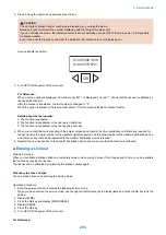
When "1" is set, startup is executed in USB import/export mode.
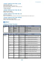
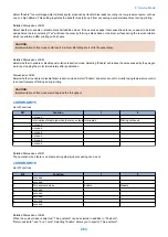
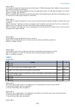
● SW05
List of Functions
Bit
Function
1
0
0
-
-
1
-
-
2
-
-
3
-
-
4
-
-
5
-
-
6
-
-
7
Inhibition of export of password in
address book
Inhibited
Not inhibited
• Detailed Discussions of Bit 7
Select whether to inhibit export of the password in the address book.
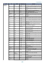
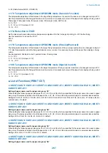
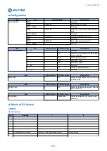
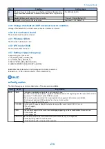
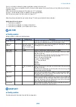
● SW09
List of Functions
Bit
Function
1
0
0
PS > Display/hide data protocol
menu
Displayed
Hide
1
Long length setting
ON
OFF
2
-
-
3
Forced invalidity of uniFLOW
ON
OFF
4
-
-
5
-
-
6
-
-
7
-
-
• Detailed Discussions of Bit 0
You can select whether to disable export of PWD in the address book.
Default: 0
• Detailed Discussions of Bit 1
You can select whether to enable long length setting (to extend the range of user-defined size).
Default: 0
• Detailed Discussions of Bit 3
Select whether to set the forced invalidity of uniFLOW.
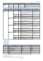
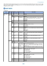
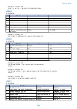
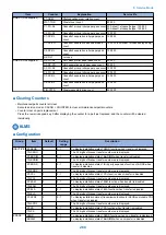
● SW11
List of functions
Bit
Function
1
0
0
Secured print setting
Disabled
Enabled
1
To set operation when secured print is disabled.
Handled as a normal job
Resulting in #0853 error
2
Operation setting of secured print
when the uniFLOW is enabled
Disable the secured print
Follow the secured print setting
(SYSTEM>SW11 Bit0)
3
Operation setting
when a secured print job is canceled
Display the password entry
screen
Not display the password entry
screen
4
Display setting of Arabic
Displayed
Not displayed
5
Switching of sublog output of memory alloc/free log
Enabled
Disabled
8. Service Mode
272
Summary of Contents for imageRUNNER 2525 Series
Page 1: ...Revision 9 0 imageRUNNER 2530 2525 2520 Series Service Manual ...
Page 62: ...No Part name 3 Laser unit 2 Technical Explanation 52 ...
Page 119: ...Periodical Service 3 Consumable Parts and Cleaning Parts 110 Cleaning Parts 115 ...
Page 125: ...Cleaning Parts Fixing guide Transfer guide 3 Periodical Service 115 ...
Page 136: ...List of Sensors S18 S17 S16 TS2 HU1 S9 S8 S19 TS1 S11 S12 4 Disassembly Assembly 126 ...
Page 165: ...5 Remove the idler gear 1 claw 1x 4 Disassembly Assembly 155 ...
Page 172: ... 1 4 2 3 2 2 Remove the scanner motor 4 screws 4x 4 Disassembly Assembly 162 ...
Page 186: ...3 Remove the RAM PCB Release the hook 4 Disassembly Assembly 176 ...
Page 187: ...Adjustment 5 Overview 178 Basic Adjustment 180 Adjustment when Replacing the Parts 182 ...
Page 209: ...Error Jam Alarm 7 Outline 200 Error Code 201 Jam Code 213 Alarm Code 219 ...
Page 231: ...Service Mode 8 Overview 222 Details of Service Mode 225 Remote UI Service Mode 302 ...
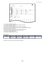
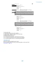
Page 314: ...Example of report display 8 Service Mode 304 ...
Page 387: ...APPENDICES Service Tools 378 General Circuit Diagram 379 ...