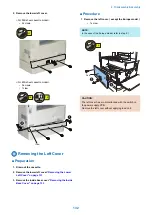
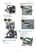


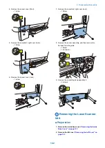
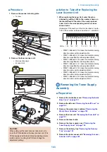


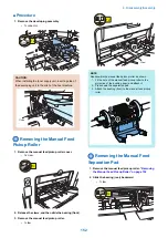
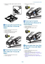

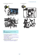

■ Procedure
1. Remove the scanner retaining plate.
• 1 screw
1x
2. Remove the laser scanner unit.
• 2 pieces of sponge
• 4 connectors
4x
CAUTION:
When pulling out the laser scanner, take care not to
touch the PCB installed on the laser scanner unit. (The
PCB is equipped with a laser intensity adjusting volume
resistor and so touching the PCB can change the
adjustment setting.)
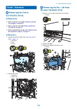
■ Action to Take after Replacing the
Laser Scanner Unit
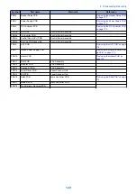
1. When replacing the Laser Unit, enter the value
obtained by adding 1,000 to the number shown on
the label affixed to the side of the newly replaced
Laser Unit in the corresponding service mode as
shown below.
(Examples: If the number on the service label is 3, enter
1,003. If the number on the service label is -1, enter 999.)
145
146
147
136
148
149
150
SW No.
-67
-5
-4
-5
• PRINT > Bitswitch > 136 Laser horizontal scanning
direction write position adjustment(A)
• PRINT > Bitswitch > 145 Laser horizontal scanning
direction magnification ratio adjustment(A-B)
• PRINT > Bitswitch > 146 Laser horizontal scanning
direction magnification ratio adjustment(A-C)
• PRINT > Bitswitch > 147 Laser horizontal scanning
direction magnification ratio adjustment(A-D)
• PRINT > Bitswitch > 148 Laser horizontal scanning
direction write position adjustment(A-B)
• PRINT > Bitswitch > 149 Laser horizontal scanning
direction write position adjustment(A-C)
• PRINT > Bitswitch > 150 Laser horizontal scanning
direction write position adjustment(A-D)
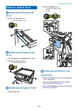
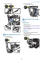
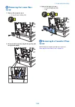
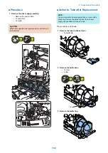
Removing the Toner Supply
Assembly
■ Preparation
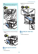
1. Remove the inside base cover.
2. Remove the left cover.
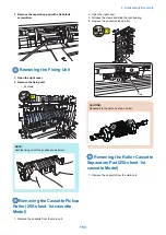
3. Remove the waste toner container.
Waste Toner Container” on page 150
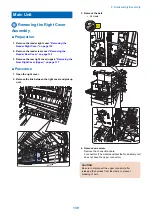
4. Remove the drum unit.
5. Remove the toner bottle.
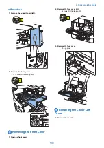
6. Remove the toner supply cover.
Toner Supply Cover” on page 134
8. Remove the laser scanner unit.
4. Disassembly/Assembly
143
Summary of Contents for imageRUNNER 2525 Series
Page 1: ...Revision 9 0 imageRUNNER 2530 2525 2520 Series Service Manual ...
Page 62: ...No Part name 3 Laser unit 2 Technical Explanation 52 ...
Page 119: ...Periodical Service 3 Consumable Parts and Cleaning Parts 110 Cleaning Parts 115 ...
Page 125: ...Cleaning Parts Fixing guide Transfer guide 3 Periodical Service 115 ...
Page 136: ...List of Sensors S18 S17 S16 TS2 HU1 S9 S8 S19 TS1 S11 S12 4 Disassembly Assembly 126 ...
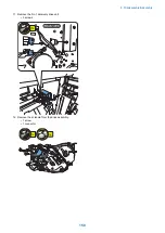
Page 165: ...5 Remove the idler gear 1 claw 1x 4 Disassembly Assembly 155 ...
Page 172: ... 1 4 2 3 2 2 Remove the scanner motor 4 screws 4x 4 Disassembly Assembly 162 ...
Page 186: ...3 Remove the RAM PCB Release the hook 4 Disassembly Assembly 176 ...
Page 187: ...Adjustment 5 Overview 178 Basic Adjustment 180 Adjustment when Replacing the Parts 182 ...
Page 209: ...Error Jam Alarm 7 Outline 200 Error Code 201 Jam Code 213 Alarm Code 219 ...
Page 231: ...Service Mode 8 Overview 222 Details of Service Mode 225 Remote UI Service Mode 302 ...
Page 314: ...Example of report display 8 Service Mode 304 ...
Page 387: ...APPENDICES Service Tools 378 General Circuit Diagram 379 ...