


Operation
Power Switch
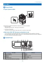
■ Types of power switch
Main power switch
Control panel power switch
This machine is equipped with the Main Power Switch and Control Panel Power Switch.
1. Main Power Switch
This switch is used to turn OFF / ON the power of host machine.
2. Control Panel Power Switch
This switch is to shift the machine to power-save mode or to restore it to normal mode.
■ How to turn ON / OFF the power and points to note
• To turn off the power, turn off the Main power Switch. (Conventional shutdown sequence operation is not required.)
• After power-off (After the Main power Switch is turned off), do not reactivate the Main power Switch until a screen disappears.
• do not turn off the power while download is processing.
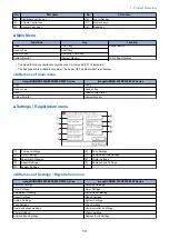
Control Panel
[1]
[2]
[3]
[4]
[5]
[6]
[7]
[8]
[9]
[10]
[11]
[12]
[15]
[16]
[13]
[14]
[17]
[18]
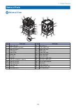
No.
Part name
No.
Part name
[1]
Touch panel display
[10]
Stop key
[2]
Display Contrast dial
[11]
Start key
[3]
COPY key
[12]
Main Power Indicator
[4]
SEND key
[13]
Error Indicator
[5]
SCAN/OPTIONS key
[14]
Processing/Data Indicator
[6]
Control Panel Power Switch (Sub Power Supply)
[15]
Clear key
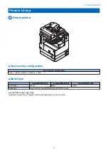
1. Product Overview
18
Summary of Contents for imageRUNNER 2525 Series
Page 1: ...Revision 9 0 imageRUNNER 2530 2525 2520 Series Service Manual ...
Page 62: ...No Part name 3 Laser unit 2 Technical Explanation 52 ...
Page 119: ...Periodical Service 3 Consumable Parts and Cleaning Parts 110 Cleaning Parts 115 ...
Page 125: ...Cleaning Parts Fixing guide Transfer guide 3 Periodical Service 115 ...
Page 136: ...List of Sensors S18 S17 S16 TS2 HU1 S9 S8 S19 TS1 S11 S12 4 Disassembly Assembly 126 ...
Page 165: ...5 Remove the idler gear 1 claw 1x 4 Disassembly Assembly 155 ...
Page 172: ... 1 4 2 3 2 2 Remove the scanner motor 4 screws 4x 4 Disassembly Assembly 162 ...
Page 186: ...3 Remove the RAM PCB Release the hook 4 Disassembly Assembly 176 ...
Page 187: ...Adjustment 5 Overview 178 Basic Adjustment 180 Adjustment when Replacing the Parts 182 ...
Page 209: ...Error Jam Alarm 7 Outline 200 Error Code 201 Jam Code 213 Alarm Code 219 ...
Page 231: ...Service Mode 8 Overview 222 Details of Service Mode 225 Remote UI Service Mode 302 ...
Page 314: ...Example of report display 8 Service Mode 304 ...
Page 387: ...APPENDICES Service Tools 378 General Circuit Diagram 379 ...