


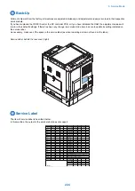
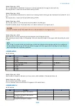


Back-Up
At time of shipment from the factory, all machines are adjusted individually, and adjustment values are recorded in their respective
service labels.
If you have replaced the CCD/CIS unit or the DC controller PCB, or if you have initialized the RAM, the adjustment values will
return to their default settings. If there has been any change in a service mode item, be sure to update its setting indicated on
the service label.
As necessary, make use of the space in the service label (as when recording an item not found on the label).
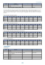
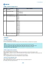
Service Label: behind the rear cover (right)
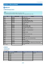
Service Label
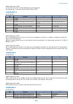
The item of service kabel is described below.
In this machine, the output of the service label does not support.
FACTORY
1
2
3
FACTORY
1
2
3
034
xxx
ADJ-X-MG
xxx
035
xxx
036
xxx
W-PLT-X
xxx
037
xxx
W-PLT-Y
xxx
038
xxx
W-PLT-Z
xxx
054
xxx
50_RG
xxx
136
xxx
50_GB
xxx
140
xxx
100_RG
xxx
141
xxx
100_GB
xxx
142
xxx
MTF3-M1
xxx
143
xxx
MTF3-M2
xxx
145
xxx
MTF3-M3
xxx
146
xxx
MTF3-M4
xxx
147
xxx
MTF3-M5
xxx
148
xxx
MTF3-M6
xxx
149
xxx
MTF3-M7
xxx
150
xxx
MTF3-M8
xxx
㸡
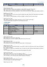
SCAN> READER> ADJUST> ADJ-XY>
MTF3-M9
xxx
ADJ-X
xxx
㸡
SCAN> READER> ADJUST> PASCAL>
ADJ-Y
xxx
OFST-P-K
xxx
ADJ-S
xxx
㸡
SCAN> FEEDER> ADJUST>
ADJ-Y-DF
xxx
DOCST
xxx
STRD-POS
xxx
LA-SPEED
xxx
DOC-LNGH
xxx
Body No
㸸
#PRINT> #PRINT NUMERIC>
㸡
SCAN> READER> ADJUST> ADJ-XY>
㸡
SCAN> READER> ADJUST> CCD>
8. Service Mode
224
Summary of Contents for imageRUNNER 2525 Series
Page 1: ...Revision 9 0 imageRUNNER 2530 2525 2520 Series Service Manual ...
Page 62: ...No Part name 3 Laser unit 2 Technical Explanation 52 ...
Page 119: ...Periodical Service 3 Consumable Parts and Cleaning Parts 110 Cleaning Parts 115 ...
Page 125: ...Cleaning Parts Fixing guide Transfer guide 3 Periodical Service 115 ...
Page 136: ...List of Sensors S18 S17 S16 TS2 HU1 S9 S8 S19 TS1 S11 S12 4 Disassembly Assembly 126 ...
Page 165: ...5 Remove the idler gear 1 claw 1x 4 Disassembly Assembly 155 ...
Page 172: ... 1 4 2 3 2 2 Remove the scanner motor 4 screws 4x 4 Disassembly Assembly 162 ...
Page 186: ...3 Remove the RAM PCB Release the hook 4 Disassembly Assembly 176 ...
Page 187: ...Adjustment 5 Overview 178 Basic Adjustment 180 Adjustment when Replacing the Parts 182 ...
Page 209: ...Error Jam Alarm 7 Outline 200 Error Code 201 Jam Code 213 Alarm Code 219 ...
Page 231: ...Service Mode 8 Overview 222 Details of Service Mode 225 Remote UI Service Mode 302 ...
Page 314: ...Example of report display 8 Service Mode 304 ...
Page 387: ...APPENDICES Service Tools 378 General Circuit Diagram 379 ...