


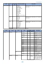
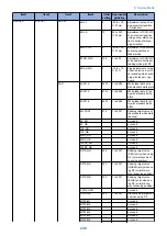


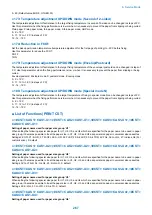

● 165: Leading edge frame length when performing SEND SCAN using the Copyboard (0.1
mm)
As the value is incremented by 1, the image position moves to the trailing edge side by 0.1mm.
● 168: Leading edge frame length when performing SEND SCAN using the ADF (0.1 mm)
As the value is incremented by 1, the image position moves to the trailing edge side by 0.1mm.
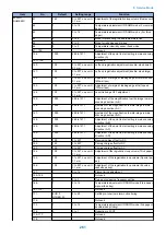
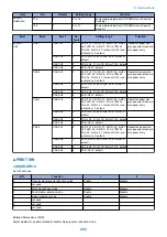
● 193: ADF special paper standard size: to prevent false recognition of LGL
This setting is used when using a standard size of special paper that cannot be recognized by ADF. (When the paper is recognized
incorrectly as LEGAL)
0: LEGAL /B4R
1: FOOLSCAP
2: M_OFICIO
3: A_FOOLSCAP
4: Not used
5: G_LEGAL
6: A_OFICIO
7: B_OFICIO
8: OFICIO
9: E_OFICIO
10: F4A
11: Indian-LGL (For customization)
NOTE:
• Papers from "No.1: FOOLSCAP" to "No.9: E_OFICIO" are supported only when inch configuration is set for the original size
detection, and LGLR is replaced with any of them.
• "No.10: F4A" is supported only when AB configuration or AB/Inch configuration is set for the original size detection, and B4R
and LGLR are replaced with it.
• Operation of the original size detection of custom paper differs depending on whether special papers are supported or not.
• Mixed stacking of special papers is not supported.
• Special papers are not supported when using the Copyboard.
• APS is not supported.
• When the setting is switched, it is necessary to turn OFF and then ON the power.
<Related Service Mode>
• #SCAN > #SCAN SW > SW05
Changes "AB configuration/Inch configuration" of the original size detection
• #SYSTEM > #SYSTEM SW > SW57
Setting of paper size group
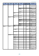
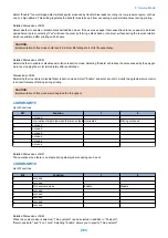
● 194: ADF special paper standard size: to prevent false recognition of LTR
This setting is used when using a standard size of special paper that is incorrectly recognized as LTR by ADF.
0: LTR /B5
1: G_LTR
2: A_LTR
3: K_LGL
4: EXE
8. Service Mode
253
Summary of Contents for imageRUNNER 2525 Series
Page 1: ...Revision 9 0 imageRUNNER 2530 2525 2520 Series Service Manual ...
Page 62: ...No Part name 3 Laser unit 2 Technical Explanation 52 ...
Page 119: ...Periodical Service 3 Consumable Parts and Cleaning Parts 110 Cleaning Parts 115 ...
Page 125: ...Cleaning Parts Fixing guide Transfer guide 3 Periodical Service 115 ...
Page 136: ...List of Sensors S18 S17 S16 TS2 HU1 S9 S8 S19 TS1 S11 S12 4 Disassembly Assembly 126 ...
Page 165: ...5 Remove the idler gear 1 claw 1x 4 Disassembly Assembly 155 ...
Page 172: ... 1 4 2 3 2 2 Remove the scanner motor 4 screws 4x 4 Disassembly Assembly 162 ...
Page 186: ...3 Remove the RAM PCB Release the hook 4 Disassembly Assembly 176 ...
Page 187: ...Adjustment 5 Overview 178 Basic Adjustment 180 Adjustment when Replacing the Parts 182 ...
Page 209: ...Error Jam Alarm 7 Outline 200 Error Code 201 Jam Code 213 Alarm Code 219 ...
Page 231: ...Service Mode 8 Overview 222 Details of Service Mode 225 Remote UI Service Mode 302 ...
Page 314: ...Example of report display 8 Service Mode 304 ...
Page 387: ...APPENDICES Service Tools 378 General Circuit Diagram 379 ...