


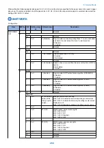
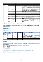

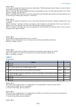


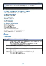

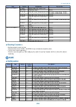

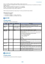


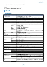

No.
Function
Setting range
25
Set the IMG1L initialization wait timer. (Unit: millisecond)
0 to 9999 (Default: 100)
26
Set the IMG1L mask setting wait timer. (Unit: millisecond)
0 to 9999 (Default: 10)
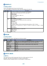
39
Set switching of the default of LDAP detailed search condition.
0: Contain
1: Not contain
2: Equal
3: Not equal
4: Begin with (Default)
5: End with
40
Set the eLA card touch sound.
0: OFF, 1: ON (Default)
41
Set the PS mode 1 (8bit).
0 to 60 (Default: 0)
42
Set the PS mode 2 (8bit).
0 to 60 (Default: 0)
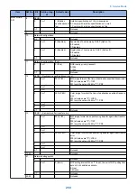
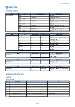
57
Set the paper size group.
Setting values and groups are as follow:
1: AB configuration (PAPER_SIZE_GROUP_
AB)
2: A configuration (PAPER_SIZE_GROUP_A)
3: INCH configuration (PAPER_SIZE_
GROUP_INCH)
4: AB/INCH configuration (PAPER_SIZE_
GROUP_AB_INCH)
The timing of initialization is as follows.
• CLEAR > ALL
• CLEAR >TYPE
• CLEAR > SERVICE DATA
• CLEAR > TEL&USER DATA (because of
synchronizing the values of ATT_ID and
SYSTEM NUMERIC)
• Select country at startup
58
Set the engine sleep (PPOWER HI) wait timer. (Unit: millisecond)
300 msec when the value is 0
0 to 9999 (Default: 0)
59
Set the timer to delay the press/waiting state of the software switch key until
the PPowerOn-enabled judgment flag is turned ON. (Unit: millisecond)
500 msec when the value is 0
0 to 9999 (Default: 0)
60
Set the Secondary Battery charging completion wait timer. (Unit: minute)
120 minutes when the value is 0.
0 to 9999 (Default: 0)
61
Set the pulse trickle charge set timer. (Unit: minute)
300 minutes when the value is 0
0 to 9999 (Default: 0)
65
Set the inquiry wait time at the time of A/D checking (tick).
0 to 9999 (Default: 3)
66
Set the RUI access delay timer. (Unit: second)
60 seconds when the value is 0
0 to 9999 (Default: 0)
67
Set the sleep 2 shift timer. (Unit: second)
12 seconds when the value is 0
0 to 9999 (Default: 0)
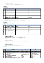
76
Set the wait time after a cancellation (E853) processing by the secured print
condition.
Wait for 500 msec when the setting value is 0 (default), and wait for [setting
value] msec when the setting value is other than 0.
0 to 9999 (Default: 0)
77
Set the initial value of the redial interval. (Unit: minute)
Setting value when the clear key is pressed
0 to 9999
78
Set the initial value of the pause time. (Unit: minute)
Setting value when the clear key is pressed
0 to 9999
79
Set the ring start time of FAX/TEL switch (detailed setting). (Unit: second)
Setting value when the clear key is pressed
0 to 9999
80
Set the ring start time of FAX/TEL switch (detailed setting). (Unit: second)
Setting value when the clear key is pressed
0 to 9999
81
Set the shift time until automatic shutdown. (Unit: second)
0 to 9999
82
120 minutes when the value of the Secondary Battery charging completion
wait timer (Unit: minute) for compliance with Lot26 is 0
*1
0 to 9999 (Default: 0)
83
180 minutes when the value of the pulse trickle charge set timer (unit: minute)
for compliance with Lot26 is 0
*1
0 to 9999 (Default: 0)
*1. An EU directive obligating to design environment-friendly products (eco-design) to facilitate energy saving
8. Service Mode
277
Summary of Contents for imageRUNNER 2525 Series
Page 1: ...Revision 9 0 imageRUNNER 2530 2525 2520 Series Service Manual ...
Page 62: ...No Part name 3 Laser unit 2 Technical Explanation 52 ...
Page 119: ...Periodical Service 3 Consumable Parts and Cleaning Parts 110 Cleaning Parts 115 ...
Page 125: ...Cleaning Parts Fixing guide Transfer guide 3 Periodical Service 115 ...
Page 136: ...List of Sensors S18 S17 S16 TS2 HU1 S9 S8 S19 TS1 S11 S12 4 Disassembly Assembly 126 ...
Page 165: ...5 Remove the idler gear 1 claw 1x 4 Disassembly Assembly 155 ...
Page 172: ... 1 4 2 3 2 2 Remove the scanner motor 4 screws 4x 4 Disassembly Assembly 162 ...
Page 186: ...3 Remove the RAM PCB Release the hook 4 Disassembly Assembly 176 ...
Page 187: ...Adjustment 5 Overview 178 Basic Adjustment 180 Adjustment when Replacing the Parts 182 ...
Page 209: ...Error Jam Alarm 7 Outline 200 Error Code 201 Jam Code 213 Alarm Code 219 ...
Page 231: ...Service Mode 8 Overview 222 Details of Service Mode 225 Remote UI Service Mode 302 ...
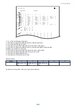
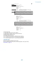
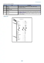
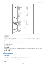
Page 314: ...Example of report display 8 Service Mode 304 ...
Page 387: ...APPENDICES Service Tools 378 General Circuit Diagram 379 ...