


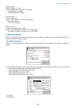
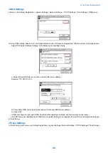


*Network is not rea
dy , try later : get
No.2 A communication test results NG! even if network setting is set properly.
Cause: No proper firmware has been installed, or E-RDS settings have not been completed.
Remedy: The following points should be checked.
1. Check the firmware compatibility of device.
2. Check network conditions such as proxy server settings and so on.
3. Check E-RDS setting.
a) Check the communication log from COM-LOG.
b) If RGW-ADR or RGW-PORT setting has changed, restore default value by Servicemode > #CLEAR > ERDS-DAT.
c) If CA certificate file has changed, restore the original certificate file installed at the factory shipment to the device by using
a service support tool.
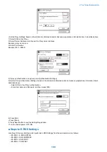
No.3 There was a log, indicating "Network is not ready, try later (No.22)" in error details of COM-LOG list.
Causes: A certain problem occurred in networking.
Remedy: Check and take actions mentioned below.
1. Check networking conditions and connections.
2. Turn on the power supply of a device and perform a communication test (Servicemode > #E-RDS > COM-TEST about 60
seconds later.
No.4 "Unknown error" is displayed though a communication test has done successfully.
Causes: A certain problem was in the server side, or possibly a network load has been added.
Remedy: The following points should be checked.
1. Change data transmission schedules, and then see how things going.
2. Try again after a period of time. If the same error persists, check the UGW status with a network and UGW administrator.
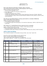
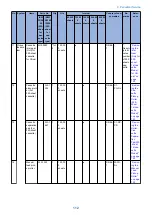
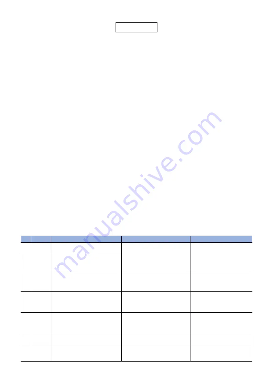
■ Error code and strings
The error information appeared to a communication test log is as follows. ( Here, "server" means UGW)
By error list, error No.1 and No.2 display only an error character strings.
Error No 3 henceforth, these are displayed in the following form.
[*][Error character strings] : [Method name] [Server side detailed error]
*: Error character strings head "*" is added to the error generated by the communication
test.
No.
Code
Error character strings
Causes
Remedy
1
0500 0003 SUSPEND: Communication test is not
performed.
The communication test had not been
performed, though E-RDS is enabled.
Select and perform Servicemode >
#E-RDS > COM-TEST.
2
0xxx 00f2 Event Registration is Failed
Processing (event processing) within
the device has failed.
Turn the device OFF/ ON. If the er-
ror persists, replace the device sys-
tem software. (Upgrade)
3
8xxx 2001 URL Scheme error(not https)
The header of the URL of the registered
UGW is not in https format.
Check that the value of Service
mode > #E-RDS > RGW-ADR is
https://a01. ugwdevice.net/ugw/
agentif010.
4
8xxx 200A Server connection error
Displayed in the event of a TCP/IP com-
munication fault. Also displayed when
an attempt is made at communication
with the device IP address not set.
Check the network connection, as
per the initial procedures described
in the troubleshooting.
5
8xxx 2002 URL server specified is illegal
A URL different to that specified by the
UGW has been set.
Check that the value of Service
mode > #E-RDS > RGW-ADR can
be https:// a01.ugwdevice.net/ugw/
agentif010.
6
8xxx 2014 Proxy connection error
Could not connect to proxy server due
to improper address.
Check proxy server address and
re- enter as needed.
7
8xxx 201E Proxy authentication error
Proxy authentication is failed.
Check the user name and pass-
word required in order to login to
the proxy, and re-enter as needed.
2. Technical Explanation
105
Summary of Contents for imageRUNNER 2525 Series
Page 1: ...Revision 9 0 imageRUNNER 2530 2525 2520 Series Service Manual ...
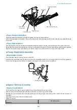
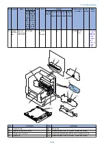
Page 62: ...No Part name 3 Laser unit 2 Technical Explanation 52 ...
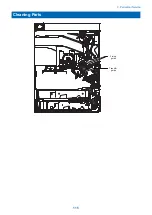
Page 119: ...Periodical Service 3 Consumable Parts and Cleaning Parts 110 Cleaning Parts 115 ...
Page 125: ...Cleaning Parts Fixing guide Transfer guide 3 Periodical Service 115 ...
Page 136: ...List of Sensors S18 S17 S16 TS2 HU1 S9 S8 S19 TS1 S11 S12 4 Disassembly Assembly 126 ...
Page 165: ...5 Remove the idler gear 1 claw 1x 4 Disassembly Assembly 155 ...
Page 172: ... 1 4 2 3 2 2 Remove the scanner motor 4 screws 4x 4 Disassembly Assembly 162 ...
Page 186: ...3 Remove the RAM PCB Release the hook 4 Disassembly Assembly 176 ...
Page 187: ...Adjustment 5 Overview 178 Basic Adjustment 180 Adjustment when Replacing the Parts 182 ...
Page 209: ...Error Jam Alarm 7 Outline 200 Error Code 201 Jam Code 213 Alarm Code 219 ...
Page 231: ...Service Mode 8 Overview 222 Details of Service Mode 225 Remote UI Service Mode 302 ...
Page 314: ...Example of report display 8 Service Mode 304 ...
Page 387: ...APPENDICES Service Tools 378 General Circuit Diagram 379 ...