


Original Exposure System
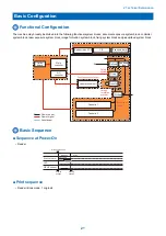
Overview
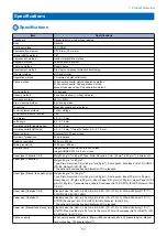
■ Specifications/controls/functions
The major specifications, controls and functions of the original exposure system are described below.
Item
Specification/function
Original exposure
LED
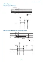
Original scan
In book mode
Original scan is performed by moving the contact image sensor (CIS).
In ADF mode
Original stream reading is performed with the contact image sensor (CIS) fixed.
Read resolution
B/W: 600 dpi (main scanning) x 600 dpi (sub scanning) (Color SEND): 300 dpi (sub
scanning)
Gradation
256 gradation
Carriage position detection
Contact image sensor (CIS) HP sensor (S31)
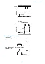
Magnification
Magnification
25% to 200%
Main scanning direction
Image is processed on main controller PCB
Sub scanning direction
In book mode: speed change by carriage travel, image process on main controller
PCB *1
In ADF mode: original feed speed change, image process on main controller PCB
*1
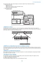
Lens
Rod lens array
CMOS sensor
Number of lines:1
Number of pixels: Total 7488 (incl. 7276 effective pixels)
Maximum original scan width: 297mm
CIS drive control
Drive control by reader motor (M31)
Original size de-
tection
In book mode
Main scanning direction: by reflection sensor (AB/INCH)
Sub scanning direction: by reflection sensor (AB/INCH)
In ADF mode
Main scanning direction: by photo interrupter on DADF
Sub scanning direction: by photo interrupter on DADF
*1 Controls differ depending on magnifications. Refer to [Magnifications] for more information.
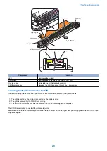
■ Major Components
Following shows major components of document exposure system.
M31
S36(2B)
S36(2A)
S37
S35
S34
PCB2
S33
S32
H5
H5
S31
CIS
Item
Notation
Specification/function
Scanner motor
M31
Pulse motor: controls the carriage drive
2. Technical Explanation
23
Summary of Contents for imageRUNNER 2525 Series
Page 1: ...Revision 9 0 imageRUNNER 2530 2525 2520 Series Service Manual ...
Page 62: ...No Part name 3 Laser unit 2 Technical Explanation 52 ...
Page 119: ...Periodical Service 3 Consumable Parts and Cleaning Parts 110 Cleaning Parts 115 ...
Page 125: ...Cleaning Parts Fixing guide Transfer guide 3 Periodical Service 115 ...
Page 136: ...List of Sensors S18 S17 S16 TS2 HU1 S9 S8 S19 TS1 S11 S12 4 Disassembly Assembly 126 ...
Page 165: ...5 Remove the idler gear 1 claw 1x 4 Disassembly Assembly 155 ...
Page 172: ... 1 4 2 3 2 2 Remove the scanner motor 4 screws 4x 4 Disassembly Assembly 162 ...
Page 186: ...3 Remove the RAM PCB Release the hook 4 Disassembly Assembly 176 ...
Page 187: ...Adjustment 5 Overview 178 Basic Adjustment 180 Adjustment when Replacing the Parts 182 ...
Page 209: ...Error Jam Alarm 7 Outline 200 Error Code 201 Jam Code 213 Alarm Code 219 ...
Page 231: ...Service Mode 8 Overview 222 Details of Service Mode 225 Remote UI Service Mode 302 ...
Page 314: ...Example of report display 8 Service Mode 304 ...
Page 387: ...APPENDICES Service Tools 378 General Circuit Diagram 379 ...