

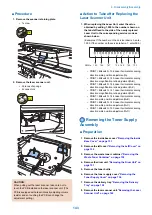


1. Enter the value indicated on the platen glass in the
following service mode:
SCAN > READER > ADJUST > CCD > W-PLT-X/Y/Z
(Input of standard white plate data)
2. Enter the service mode, and then select the
following:
SCAN > READER > FUNCTION > CCD > DF-
WLVL1/2/3/4 (DF white level adjustment)
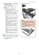
1. Place a sheet of paper that the user usually uses
on the platen glass,
enter the service mode, and then select SCAN >
READER > FUNCTION > CCD > DFWLVL1.
Read the white level in the BOOK mode.
(Check the transparency of the glass for BOOK
mode.)
2. Place a sheet of paper that the user usually uses
on the DF,
enter the service mode, and then select SCAN >
READER > FUNCTION > CCD > DF-WLVL2.
Read the white level in the DF mode (stream
reading).
(Check the transparency of the glass for stream
reading.)(Read both sides of the chart.)
3. Place a sheet of paper that the user usually uses
on the platen glass,
enter the service mode, and then select SCAN >
READER > FUNCTION > CCD > DFWLVL3.
Read the white level in the BOOK mode.
(Check the transparency of the glass for BOOK
mode.)
4. Place a sheet of paper that the user usually uses
on the DF,
enter the service mode, and then select SCAN >
READER > FUNCTION > CCD > DF-WLVL4.
Read the white level in the DF mode (stream
reading).
(Check the transparency of the glass for stream
reading.)(Read both sides of the chart.)
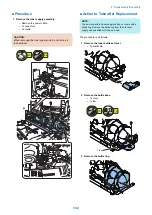
Removing the ADF Scan Glass
1. Open the platen cover (platen board cover/ADF).
2. Remove the glass retainer.
• 2 screws
3. Remove the ADF scan glass.
2x
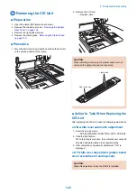
CAUTION:
• When removing the ADF scan glass, take care not
to touch the glass surface with your fingers.
• Soils on the glass surface may cause white/black
lines on images.
• If the glass surface is soiled, clean them with a lint-
free paper moistened with alcohol.
• Be sure to install the ADF scan glass with its seat
facing front left.
4. Disassembly/Assembly
147
Summary of Contents for imageRUNNER 2525 Series
Page 1: ...Revision 9 0 imageRUNNER 2530 2525 2520 Series Service Manual ...
Page 62: ...No Part name 3 Laser unit 2 Technical Explanation 52 ...
Page 119: ...Periodical Service 3 Consumable Parts and Cleaning Parts 110 Cleaning Parts 115 ...
Page 125: ...Cleaning Parts Fixing guide Transfer guide 3 Periodical Service 115 ...
Page 136: ...List of Sensors S18 S17 S16 TS2 HU1 S9 S8 S19 TS1 S11 S12 4 Disassembly Assembly 126 ...
Page 165: ...5 Remove the idler gear 1 claw 1x 4 Disassembly Assembly 155 ...
Page 172: ... 1 4 2 3 2 2 Remove the scanner motor 4 screws 4x 4 Disassembly Assembly 162 ...
Page 186: ...3 Remove the RAM PCB Release the hook 4 Disassembly Assembly 176 ...
Page 187: ...Adjustment 5 Overview 178 Basic Adjustment 180 Adjustment when Replacing the Parts 182 ...
Page 209: ...Error Jam Alarm 7 Outline 200 Error Code 201 Jam Code 213 Alarm Code 219 ...
Page 231: ...Service Mode 8 Overview 222 Details of Service Mode 225 Remote UI Service Mode 302 ...
Page 314: ...Example of report display 8 Service Mode 304 ...
Page 387: ...APPENDICES Service Tools 378 General Circuit Diagram 379 ...