


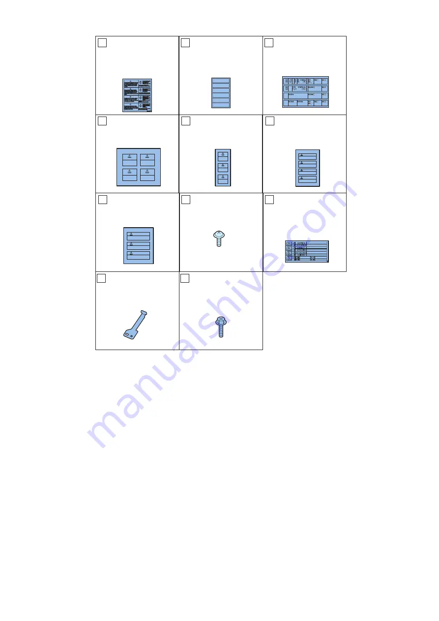
[
@
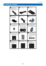
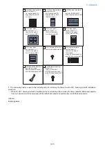
Glass cleaning/lamp
caution label x 1
(for Australia and EU
supplied with an ADF
<A type>)
>@
Glass cleaning/lamp
caution label x 1
(for Australia and EU
supplied with an ADF
<AB/INCH type>)
>@
Document size label
x 1
(only for iR2530/2525/
2520 supplied with an ADF)
>@
Finger pinch
caution label 1:x 1
(only for the model
for US with an ADF)
>@
Finger pinch
caution label 1 x 1
(only for the model
for EU with an ADF)
>@
Finger pinch
caution label 2 x 1
(only for the model
for EU with an ADF)
>@
Finger pinch
caution label 2 x 1
(only for the model
for US with an ADF)
>@
TP screw (M3 x 6) x 1
(only for Australia model)
[24]High temperature
caution label x 1
(only for the model
for CN and
with 250-sheet cassette 1
and 550-sheet cassette 2)
>@
Connecting Fixture x 1
(only for the model
with 250-sheet cassette 1
and 550-sheet cassette 2)*1
>@
RS tightening screw
(M3x8.5) x 1
(only for the model
with 250-sheet cassette 1
and 550-sheet cassette 2)*1
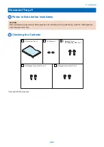
*1: The connecting fixture is used for the following case. For attaching the fixture, see the CST. Feeding Unit-AE1 installation
procedure.
• When the CST. Feeding Unit-AE1 is installed to the host machine after removing the lower cassette (550-sheet cassette)
from the host model which is equipped with the 250-sheet cassette, cassette spacer and 550-sheet cassette.
<Others>
Including guides
9. Installation
311
Summary of Contents for imageRUNNER 2525 Series
Page 1: ...Revision 9 0 imageRUNNER 2530 2525 2520 Series Service Manual ...
Page 62: ...No Part name 3 Laser unit 2 Technical Explanation 52 ...
Page 119: ...Periodical Service 3 Consumable Parts and Cleaning Parts 110 Cleaning Parts 115 ...
Page 125: ...Cleaning Parts Fixing guide Transfer guide 3 Periodical Service 115 ...
Page 136: ...List of Sensors S18 S17 S16 TS2 HU1 S9 S8 S19 TS1 S11 S12 4 Disassembly Assembly 126 ...
Page 165: ...5 Remove the idler gear 1 claw 1x 4 Disassembly Assembly 155 ...
Page 172: ... 1 4 2 3 2 2 Remove the scanner motor 4 screws 4x 4 Disassembly Assembly 162 ...
Page 186: ...3 Remove the RAM PCB Release the hook 4 Disassembly Assembly 176 ...
Page 187: ...Adjustment 5 Overview 178 Basic Adjustment 180 Adjustment when Replacing the Parts 182 ...
Page 209: ...Error Jam Alarm 7 Outline 200 Error Code 201 Jam Code 213 Alarm Code 219 ...
Page 231: ...Service Mode 8 Overview 222 Details of Service Mode 225 Remote UI Service Mode 302 ...
Page 314: ...Example of report display 8 Service Mode 304 ...
Page 387: ...APPENDICES Service Tools 378 General Circuit Diagram 379 ...