


1
2
3
4
5
6
7
8
9
10
1
2
3
4
5
6
7
8
9
10
F
E
D
C
B
A
F
E
D
C
B
A
P.6
FM4-3342
FM4-3341
GND
+5V
CCVI CP ENB
CCVI KYU COUNT
CCVI CL BW L
USB A
USB(H)
J8103
J8110
SDcard
J8104
USB(D)
J8111
LAN
Ba
tt
e
ry
(+)
(-)
Se
c
o
nd
ary
1
2
N.
C.
G
N
D
G
N
D
G
N
D
VH(+)
AG
N
D
+1
2
V
SNOO
P
T
X_
O
UT
RX_
IN
2
3
4
5
6
7
8
9
10
11
12
13
14
15
16
17
18
19
20
21
22
FFC
J1
+5
V
G
N
D
+3
.3V
CI
VS
DC
LI
M
SRD
PRD
HR
D
CML
D
L
PRD
CI
1
CI
2
N.
C.
HOO
K1
HOO
K2
CAI
DD
L
PL1
L
PL2
IPSEL
N.
C.
+5
V
1
VH(-)
CT1
CT2
T2
N.C.
L1
L2
T1
1
2
GND
GND
CARD_READER_TX
CARD_READER_COUNT
B_CRDY
C_CRDY
B_PRDY
C_PRDY
COIN_TX
COIN_RX
VOUT1
VOUT2
GND
VCC(5Vor3.3V)
GND
J81
49
J8103
G
ND
J8124
21
19
17
15
13
11
9
7
5
3
1
J8127
2
4
6
8
10
12
14
16
18
20
22
J2
USB
USB(H)
G
N
D
+2
4
V
CI
CN
T
_OUT
CARD_READER_RX
CCVI LARGE SMALL B
CCVI OPTION
+5V
GND
+2
4V
MODEM PCB
1
2
3
4
5
6
7
J81
1
7
1
2
3
4
5
6
7
J99
0
4
J25
7
1
1
2
3
4
5
1
2
3
4
5
J99
0
1
2
1
J8134
1
2
3
4
J001
2
1
J002
1
1
1
0
9
8
2
3
4
5
6
1
7
J0
0
02
1
2
J8
1
40
2
1
9
8
2
3
4
5
6
1
7
J81
1
8
1
2
3
J8146
1
2
3
4
5
6
7
J0
0
4
1
2
3
4
5
6
J8147
1
2
3
4
5
6
J02
1
2
3
4
5
6
7
J3
2
1
J4
2
3
1
J0
0
3
2
1
J9999
2
1
J112
SP1
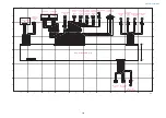
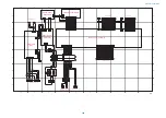
MODEM PCB
Modular
PCB
NCU PCB
Main Controller PCB (3/3)
Speaker (Option)
to Power Supply PCB
Card Reader
to Coin Vendor
Control Interface
Cable
USB hub PCB
FAX BOX
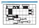
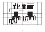
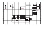
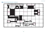
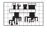
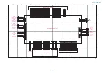
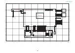
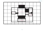
General Circuit Diagram
384
Summary of Contents for imageRUNNER 2525 Series
Page 1: ...Revision 9 0 imageRUNNER 2530 2525 2520 Series Service Manual ...
Page 62: ...No Part name 3 Laser unit 2 Technical Explanation 52 ...
Page 119: ...Periodical Service 3 Consumable Parts and Cleaning Parts 110 Cleaning Parts 115 ...
Page 125: ...Cleaning Parts Fixing guide Transfer guide 3 Periodical Service 115 ...
Page 136: ...List of Sensors S18 S17 S16 TS2 HU1 S9 S8 S19 TS1 S11 S12 4 Disassembly Assembly 126 ...
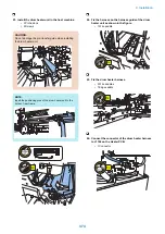
Page 165: ...5 Remove the idler gear 1 claw 1x 4 Disassembly Assembly 155 ...
Page 172: ... 1 4 2 3 2 2 Remove the scanner motor 4 screws 4x 4 Disassembly Assembly 162 ...
Page 186: ...3 Remove the RAM PCB Release the hook 4 Disassembly Assembly 176 ...
Page 187: ...Adjustment 5 Overview 178 Basic Adjustment 180 Adjustment when Replacing the Parts 182 ...
Page 209: ...Error Jam Alarm 7 Outline 200 Error Code 201 Jam Code 213 Alarm Code 219 ...
Page 231: ...Service Mode 8 Overview 222 Details of Service Mode 225 Remote UI Service Mode 302 ...
Page 314: ...Example of report display 8 Service Mode 304 ...
Page 387: ...APPENDICES Service Tools 378 General Circuit Diagram 379 ...