
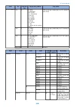


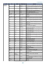
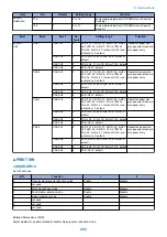


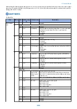
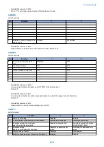


Item
No.
Default
Setting range
Function
#PRINT
NUMERIC
61:
145
0 to 227, one unit =
0.1 mm
Adjustment of the registration loop volume (Duplex unit)
62:
7
0 to 14
Temperature adjustment UP/DOWN mode (For normal
paper)
63:
7
0 to 14
Temperature adjustment UP/DOWN mode. (For thick
paper)
64:
2
0 to 4
Mode for preventing the end temperature rise
65:
0
0 to 2
Mode for reducing sand image
66:
0
0 to 3
Temperature/ Humidity sensor fixed mode
67:- 135:
Not used
136:
1000
488 to 1511
Adjustment of the point to start writing in main scanning
direction (A)
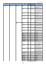
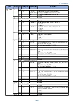
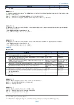
137:- 139:
Not used
140:
100
0 to 227, one unit =
0.1 mm
Left-end registration adjustment (double- sided small)
141:
100
0 to 227, one unit =
0.1 mm
Left-end registration adjustment (double- sided large)
142:
100
0 to 227, one unit =
0.1 mm
Adjustment of margin at leading edge at normal speed
(230mm/sec)
143:
100
0 to 227, one unit =
0.1 mm
Adjustment of margin at leading edge at half speed
(137mm/sec)
144:
100
0 to 227, one unit =
0.1 mm
Laser trail edge OFF adjustment
145:
1000
488 to 1511
Adjustment of the magnification to write image in main
scanning direction (A-B)
146:
1000
488 to 1511
djustment of the magnification to write image in main
scanning direction (A-C)
147:
1000
488 to 1511
djustment of the magnification to write image in main
scanning direction (A-D)
148:
1000
488 to 1511
Adjustment of the point to start writing in main scanning
direction (A-B)
149:
1000
488 to 1511
Adjustment of the point to start writing in main scanning
direction (A-C)
150:
1000
488 to 1511
Adjustment of the point to start writing in main scanning
direction (A-D)
151:
100
0 to 227
Developing bias offset for DC
152:
100
0 to 227
Primary charge offset for DC
153:
100
0 to 227
Primary charge offset for AC
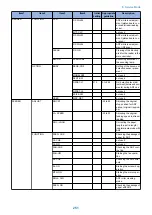
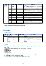
154:
100
0 to 227, one unit =
0.1 mm
Adjustment of the registration loop volume (Thick paper)
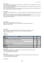
155:
100
0 to 227, one unit =
0.1 mm
Adjustment of the registration loop volume (Special pa-
per)
156:
100
0 to 227, one unit =
0.1 mm
Adjustment of the registration loop volume (Envelop
cassette pickup)
157:
7
0 to 14
Pickup timing adjustment
158:-164:
Not used
165:
0
0 to 3
Fixing auto cleaning frequency setting
166:
7
0 to 14
Temperature adjustment UP/DOWN mode (Plain paper,
manual feed tray)
167: 170:
Not used
171:
EUR:0
OTHER:33
0 to 40
Set Bk pre-toner low alarm notice timing
172:
Not used
173:
7
0 to 14
Temperature adjustment UP/DOWN mode (2nd page of
double-sided printing)
174:
0
0 to 1
Reduction in FCOT
175:-177:
Not used
178:
Not used
8. Service Mode
261
Summary of Contents for imageRUNNER 2525 Series
Page 1: ...Revision 9 0 imageRUNNER 2530 2525 2520 Series Service Manual ...
Page 62: ...No Part name 3 Laser unit 2 Technical Explanation 52 ...
Page 119: ...Periodical Service 3 Consumable Parts and Cleaning Parts 110 Cleaning Parts 115 ...
Page 125: ...Cleaning Parts Fixing guide Transfer guide 3 Periodical Service 115 ...
Page 136: ...List of Sensors S18 S17 S16 TS2 HU1 S9 S8 S19 TS1 S11 S12 4 Disassembly Assembly 126 ...
Page 165: ...5 Remove the idler gear 1 claw 1x 4 Disassembly Assembly 155 ...
Page 172: ... 1 4 2 3 2 2 Remove the scanner motor 4 screws 4x 4 Disassembly Assembly 162 ...
Page 186: ...3 Remove the RAM PCB Release the hook 4 Disassembly Assembly 176 ...
Page 187: ...Adjustment 5 Overview 178 Basic Adjustment 180 Adjustment when Replacing the Parts 182 ...
Page 209: ...Error Jam Alarm 7 Outline 200 Error Code 201 Jam Code 213 Alarm Code 219 ...
Page 231: ...Service Mode 8 Overview 222 Details of Service Mode 225 Remote UI Service Mode 302 ...
Page 314: ...Example of report display 8 Service Mode 304 ...
Page 387: ...APPENDICES Service Tools 378 General Circuit Diagram 379 ...