


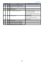

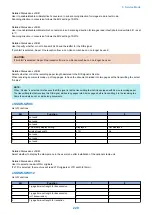


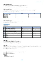

Alarm Code
Title
A. Movement /B. Cause /C. Measures
37
-
0005
Repair Request (Corrupt Image/Other Problems)
-
37
-
0006
Repair Request (Paper Jam/Other Problems)
-
37
-
0007
Repair Request (Corrupt Image/Paper Jam/Other Prob-
lems)
-
37
-
1000
Repair Request Cancel
-
37
-
2000
Repair Completed
-
50
-
0010
Alarm due to original separation failure
Movement: Nothing in particular.
Cause: Condition unable to separate 1st sheet of orig-
inal from the ADF occurs 3 times.
Measures: Check rotation of the Pickup Motor (M1) ->
Check the life of the Pickup Roller -> Check if paper lint
is at the Pickup Slot.
50
-
0012
Feed Motor Fan alarm
Movement: No change.
CAUSE: Disconnection of the ADF Exhaust Fan (FM1)
or the failure of ADF Exhaust Fan (FM1)
Measures: Check the connector -> Replace the ADF
Exhaust Fan (FM1)
85
-
0001
System error clear
-
85
-
0002
Auto-restore caused by service replacement
-
85
-
0003
Auto-restore caused by service replacement
-
85
-
0004
Auto-restore caused by service replacement
-
85
-
0005
Auto-restore caused by service replacement
-
7. Error/Jam/Alarm
220
Summary of Contents for imageRUNNER 2525 Series
Page 1: ...Revision 9 0 imageRUNNER 2530 2525 2520 Series Service Manual ...
Page 62: ...No Part name 3 Laser unit 2 Technical Explanation 52 ...
Page 119: ...Periodical Service 3 Consumable Parts and Cleaning Parts 110 Cleaning Parts 115 ...
Page 125: ...Cleaning Parts Fixing guide Transfer guide 3 Periodical Service 115 ...
Page 136: ...List of Sensors S18 S17 S16 TS2 HU1 S9 S8 S19 TS1 S11 S12 4 Disassembly Assembly 126 ...
Page 165: ...5 Remove the idler gear 1 claw 1x 4 Disassembly Assembly 155 ...
Page 172: ... 1 4 2 3 2 2 Remove the scanner motor 4 screws 4x 4 Disassembly Assembly 162 ...
Page 186: ...3 Remove the RAM PCB Release the hook 4 Disassembly Assembly 176 ...
Page 187: ...Adjustment 5 Overview 178 Basic Adjustment 180 Adjustment when Replacing the Parts 182 ...
Page 209: ...Error Jam Alarm 7 Outline 200 Error Code 201 Jam Code 213 Alarm Code 219 ...
Page 231: ...Service Mode 8 Overview 222 Details of Service Mode 225 Remote UI Service Mode 302 ...
Page 314: ...Example of report display 8 Service Mode 304 ...
Page 387: ...APPENDICES Service Tools 378 General Circuit Diagram 379 ...