

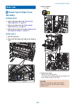


Removing the Cassette Pickup
Assembly 1 (250-sheet 1st
cassette Model)
■ Preparation
1. Draw out the cassette.
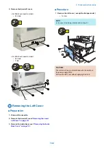
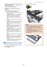
2. Open the right cover.
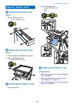
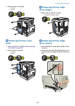
3. Remove the rear cover (right).
4. Remove the rear cover (left).
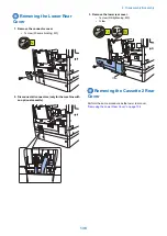
5. Remove the connector cover.
6. Remove the lower rear cover.
7. Remove the rear right cover (lower).
Right Cover (Lower)” on page 137
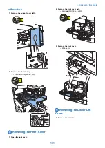
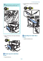
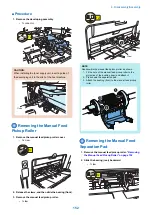
■ Procedure
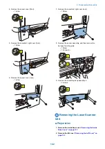
1. Remove the pulley shaft.
• 1 screw
1x
2. Remove the pulley.
• 1 belt
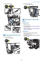
3. Remove the connection cable.
• 1 connector
1x
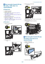
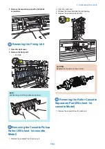
4. Remove the link between the right cover and cassette
pickup assembly.
5. Remove the cassette pickup assembly.
• 3 screws
3x
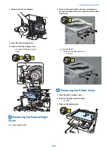
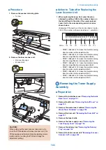
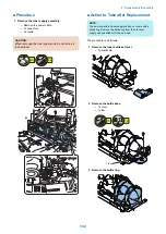
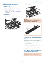
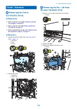
Removing the Cassette Pickup
Assembly 2 (250-sheet 1st
cassette Model)
1. Draw out the cassette 2.
2. Remove the right lower cover.
• 1 Claw
1x
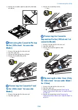
3. Open the cassette right lower cover.
4. Disassembly/Assembly
141
Summary of Contents for imageRUNNER 2525 Series
Page 1: ...Revision 9 0 imageRUNNER 2530 2525 2520 Series Service Manual ...
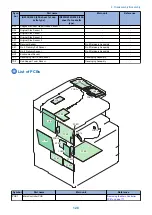
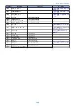
Page 62: ...No Part name 3 Laser unit 2 Technical Explanation 52 ...
Page 119: ...Periodical Service 3 Consumable Parts and Cleaning Parts 110 Cleaning Parts 115 ...
Page 125: ...Cleaning Parts Fixing guide Transfer guide 3 Periodical Service 115 ...
Page 136: ...List of Sensors S18 S17 S16 TS2 HU1 S9 S8 S19 TS1 S11 S12 4 Disassembly Assembly 126 ...
Page 165: ...5 Remove the idler gear 1 claw 1x 4 Disassembly Assembly 155 ...
Page 172: ... 1 4 2 3 2 2 Remove the scanner motor 4 screws 4x 4 Disassembly Assembly 162 ...
Page 186: ...3 Remove the RAM PCB Release the hook 4 Disassembly Assembly 176 ...
Page 187: ...Adjustment 5 Overview 178 Basic Adjustment 180 Adjustment when Replacing the Parts 182 ...
Page 209: ...Error Jam Alarm 7 Outline 200 Error Code 201 Jam Code 213 Alarm Code 219 ...
Page 231: ...Service Mode 8 Overview 222 Details of Service Mode 225 Remote UI Service Mode 302 ...
Page 314: ...Example of report display 8 Service Mode 304 ...
Page 387: ...APPENDICES Service Tools 378 General Circuit Diagram 379 ...