


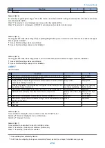


Item
SW No. Bit
Setting rang-
es
Default value
Description
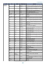
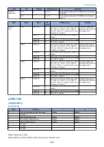
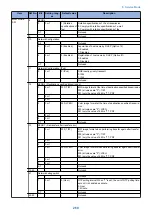
#NETWORK
SW
8
SEND 4
0
0 or 1
1 (Rotation
specifications of
fax)
Rotation specifications of I-Fax transmission
0: Comply with rotation specifications of e-mail
1: Comply with rotation specifications of fax
1-7
-
-
Not used
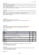
9
-
-
-
Not used
10
Network Configuration
0-2
-
-
Not used
3
0 or 1
0 (Enabled)
Acquisition of host name by DHCP (Option 12)
0: Enabled
1: Disabled
4
0 or 1
0 (Enabled)
Registration of host name by DHCP (Option 81)
0: Enabled
1: Disabled
5-7
-
-
Not used
11
Network Configuration (IPv6)
0
0 or 1
0 (IPv6)
DNS inquiry priority transport
0: IPv6
1: IPv4
1-7
-
-
Not used
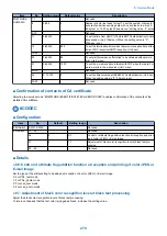
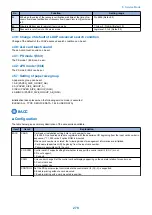
12
SEND 6 (Destination specified transmission)
0
0 or 1
000 (TIFF)
B/W image format at the time of destination specified transmission
000 (all values are "0"): TIFF
001 (only the value of bit2 is "1"): PDF
1
0 or 1
2
0 or 1
3
0 or 1
000 (JPEG)
Color image format at the time of destination specified transmis-
sion
000 (all values are "0"): JPEG
001 (only the value of bit5 is "1"): PDF
4
0 or 1
5
0 or 1
6-7
-
-
Not used
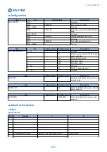
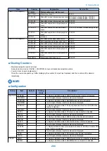
13
SEND 7 (Re-transfer after transfer error)
0
0 or 1
000 (TIFF)
B/W image format when performing transfer again after transfer
error
000 (all values are "0"): TIFF
001 (only the value of bit2 is "1"): PDF
1
0 or 1
2
0 or 1
3
0 or 1
000 (JPEG)
Color image format when performing transfer again after transfer
error
000 (all values are "0"): JPEG
001 (only the value of bit5 is "1"): PDF
4
0 or 1
5
0 or 1
6-7
-
-
Not used
14-40
-
-
-
Not used
41
Network debug switch
0
-
-
Not used
1
0 or 1
0 (Hour)
NTP polling interval When "1" is set, the unit of NTP polling time
set on UI is handled as minute.
0: Hour
1: Minute
2-7
-
-
Not used
42-50
-
-
-
Not used
8. Service Mode
269
Summary of Contents for imageRUNNER 2525 Series
Page 1: ...Revision 9 0 imageRUNNER 2530 2525 2520 Series Service Manual ...
Page 62: ...No Part name 3 Laser unit 2 Technical Explanation 52 ...
Page 119: ...Periodical Service 3 Consumable Parts and Cleaning Parts 110 Cleaning Parts 115 ...
Page 125: ...Cleaning Parts Fixing guide Transfer guide 3 Periodical Service 115 ...
Page 136: ...List of Sensors S18 S17 S16 TS2 HU1 S9 S8 S19 TS1 S11 S12 4 Disassembly Assembly 126 ...
Page 165: ...5 Remove the idler gear 1 claw 1x 4 Disassembly Assembly 155 ...
Page 172: ... 1 4 2 3 2 2 Remove the scanner motor 4 screws 4x 4 Disassembly Assembly 162 ...
Page 186: ...3 Remove the RAM PCB Release the hook 4 Disassembly Assembly 176 ...
Page 187: ...Adjustment 5 Overview 178 Basic Adjustment 180 Adjustment when Replacing the Parts 182 ...
Page 209: ...Error Jam Alarm 7 Outline 200 Error Code 201 Jam Code 213 Alarm Code 219 ...
Page 231: ...Service Mode 8 Overview 222 Details of Service Mode 225 Remote UI Service Mode 302 ...
Page 314: ...Example of report display 8 Service Mode 304 ...
Page 387: ...APPENDICES Service Tools 378 General Circuit Diagram 379 ...