


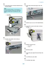
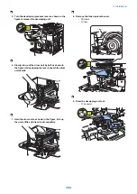


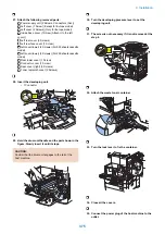


4. Attach the screw with the stubby driver, and then
connect the connector of Cassette Heater Unit to the
Connector of CST. Feeding Unit.
• 1 Screw (W sems round end; M3x6)
Connector
1x
1x
W sems round end; M3x6
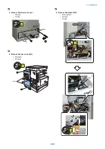
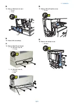
5. Attach the Heater Connector Cover
6. Attach the 2 cassettes.
7. Connect the power plug of the host machine to the
outlet.
8. Turn ON the main power switch.
9. Turn ON the heater switch.
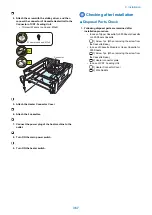
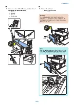
Checking after Installation
■ Disposal Parts Check
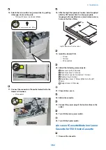
1. Following disposal parts are remained after
installation procedure.
• In case of Upper Cassette for 550 Sheets Cassette
or 250 Sheets Cassette
[1] Screw 1pc. (When removing the screw from
the Cassette Base.)
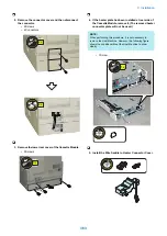
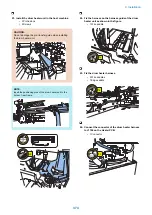
• In case of Cassette Module or Upper Cassette for
550 Sheets
[1] Screw 1pc. (When removing the screw from
the Cassette Base.)
[2] Heater connector plate
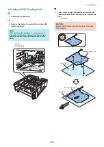
• In case of CST. Feeding Unit
[1] Heater Connector Cover
[2] Wire Saddle
9. Installation
367
Summary of Contents for imageRUNNER 2525 Series
Page 1: ...Revision 9 0 imageRUNNER 2530 2525 2520 Series Service Manual ...
Page 62: ...No Part name 3 Laser unit 2 Technical Explanation 52 ...
Page 119: ...Periodical Service 3 Consumable Parts and Cleaning Parts 110 Cleaning Parts 115 ...
Page 125: ...Cleaning Parts Fixing guide Transfer guide 3 Periodical Service 115 ...
Page 136: ...List of Sensors S18 S17 S16 TS2 HU1 S9 S8 S19 TS1 S11 S12 4 Disassembly Assembly 126 ...
Page 165: ...5 Remove the idler gear 1 claw 1x 4 Disassembly Assembly 155 ...
Page 172: ... 1 4 2 3 2 2 Remove the scanner motor 4 screws 4x 4 Disassembly Assembly 162 ...
Page 186: ...3 Remove the RAM PCB Release the hook 4 Disassembly Assembly 176 ...
Page 187: ...Adjustment 5 Overview 178 Basic Adjustment 180 Adjustment when Replacing the Parts 182 ...
Page 209: ...Error Jam Alarm 7 Outline 200 Error Code 201 Jam Code 213 Alarm Code 219 ...
Page 231: ...Service Mode 8 Overview 222 Details of Service Mode 225 Remote UI Service Mode 302 ...
Page 314: ...Example of report display 8 Service Mode 304 ...
Page 387: ...APPENDICES Service Tools 378 General Circuit Diagram 379 ...