


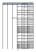


Item1
Item2
Item3
Item4
Initial
setting
Appropriate
guideline
Description
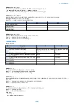
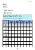
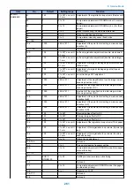
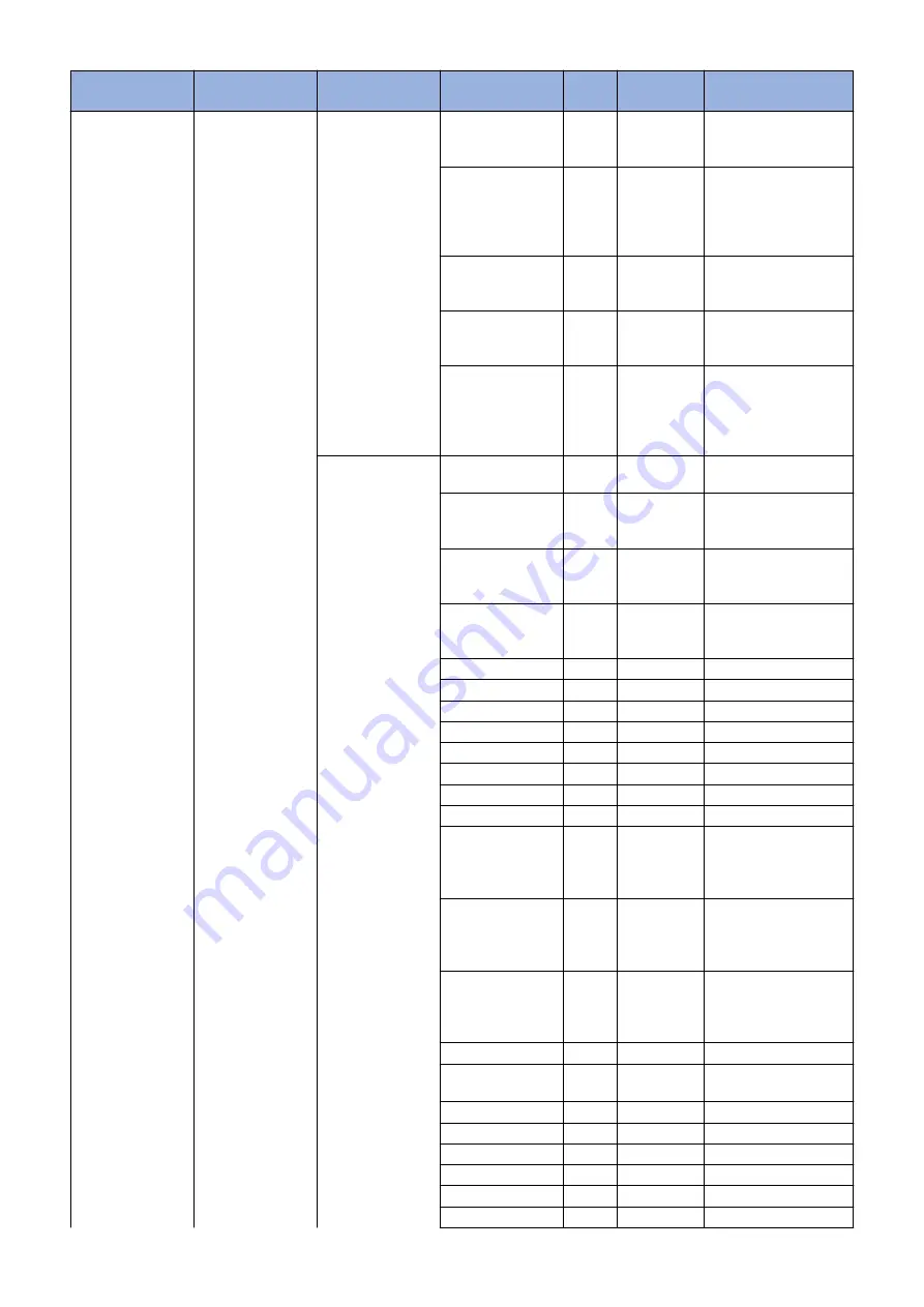
READER
ADJUST
ADJ-XY
ADJ-Y
0
-25 to +25,
1=0.1mm
Adjustment value of im-
age scan-start position
<Y-direction>
ADJ-S
75
25 to 500,
1=0.1mm
Adjustment of CCD/CIS
scan- start cell position
(image scan- start posi-
tion in horizontal scan-
ning direction)
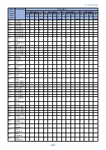
ADJ-Y-DF
0
-25 to +25,
1=0.1mm
Adjustment of horizontal
scanning position at
feeder mode
STRD-POS
100
1 to 200
Adjustment of CCD/CIS
scan position at stream-
reading mode with DF
ADJ-X-MG
0
-10 to +10,
1=0.1%
Fine adjustment of mag-
nification ration in verti-
cal scanning when scan-
ning with reader copy-
board
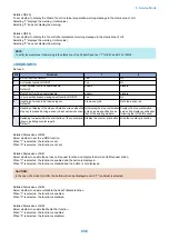
CCD
W-PLT-X
8273
1 to 9999
White label data entry
with standard white plate
W-PLT-Y
8737
1 to 9999
White label data (Y) en-
try with standard white
plate
W-PLT-Z
9427
1 to 9999
White label data (Z) en-
try with standard white
plate
SH-TRGT
272
1 to 2047
Shading target value of
the standard white plate
(backup)
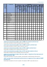
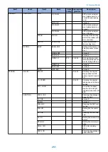
50_RG
not used
50_GB
not used
100_RG
not used
100_GB
not used
50DF_RG
not used
50DF_GB
not used
100DF_RG
not used
100DF_GB
not used
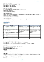
DFTAR-R
292
1 to 2047
Shading target value
(RED) entry when using
DF (normal document
scanning position)
DFTAR-G
297
1 to 2047
Shading target value
(GREEN) entry when us-
ing DF (normal docu-
ment scanning position)
DFTAR-B
294
1 to 2047
Shading target value
(BLUE) entry when us-
ing DF (normal docu-
ment scanning position)
CCD-CHNG
not used
DFTAR-K
293
1 to 2047
Black shading target val-
ue when using DF
MTF3-M1
not used
MTF3-M2
not used
MTF3-M3
not used
MTF3-M4
not used
MTF3-M5
not used
MTF3-M6
not used
8. Service Mode
249
Summary of Contents for imageRUNNER 2525 Series
Page 1: ...Revision 9 0 imageRUNNER 2530 2525 2520 Series Service Manual ...
Page 62: ...No Part name 3 Laser unit 2 Technical Explanation 52 ...
Page 119: ...Periodical Service 3 Consumable Parts and Cleaning Parts 110 Cleaning Parts 115 ...
Page 125: ...Cleaning Parts Fixing guide Transfer guide 3 Periodical Service 115 ...
Page 136: ...List of Sensors S18 S17 S16 TS2 HU1 S9 S8 S19 TS1 S11 S12 4 Disassembly Assembly 126 ...
Page 165: ...5 Remove the idler gear 1 claw 1x 4 Disassembly Assembly 155 ...
Page 172: ... 1 4 2 3 2 2 Remove the scanner motor 4 screws 4x 4 Disassembly Assembly 162 ...
Page 186: ...3 Remove the RAM PCB Release the hook 4 Disassembly Assembly 176 ...
Page 187: ...Adjustment 5 Overview 178 Basic Adjustment 180 Adjustment when Replacing the Parts 182 ...
Page 209: ...Error Jam Alarm 7 Outline 200 Error Code 201 Jam Code 213 Alarm Code 219 ...
Page 231: ...Service Mode 8 Overview 222 Details of Service Mode 225 Remote UI Service Mode 302 ...
Page 314: ...Example of report display 8 Service Mode 304 ...
Page 387: ...APPENDICES Service Tools 378 General Circuit Diagram 379 ...