


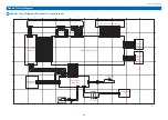
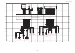
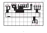


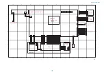

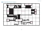
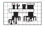

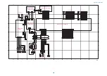
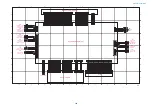
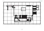
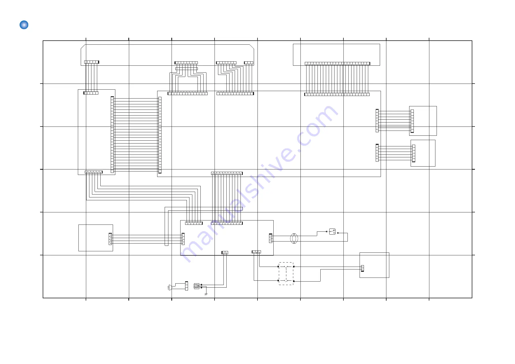
General Circuit Diagram (250-sheet 1st cassette type)
1
2
3
4
5
6
7
8
9
10
1
2
3
4
5
6
7
8
9
10
F
E
D
C
B
A
F
E
D
C
B
A
P.1
+24U_
LO
CK
GND
GND
+24V
+24V
DETEC
T
ECO_DOUT
+5VR
G
N
D
1
GND
FRAM_WP
SPD_CLK
SPD_DAT
2
3
ESS
1
G
N
D
G
N
D
PO
L
YG
ON_
M_
AC
C*
PO
L
YG
ON_
M_
F
G*
P_G
ND
UI_TXD
GND
UI_R
XD
QVGA_L
CDEN
QVGA_ST
ARTP
+3.
3
V
UI_SOF
TSW*
BKL
T
ON
QVGA_L
ATCH
P
RESET_U
I*
+3.
3
R
GND
+5R
GND
+5R
GND
QVGA_XCL
K*
QVGA_U
D0
QVGA_U
D1
QVGA_U
D2
QVGA_U
D3
GND
GND
PO
L
YG
ON_
M_
DEC*
L_GND
DDI_ITOP_OUT*
IMG1L_IMAGE_END*
L_GND
IMG1L_TXD
IMG1L_RXD
L_GND
DDI_LIVEWAKE*
DDI_PI0
DDI_DOWNLOAD*
IMG_SYS_RST*
L_GND
DDI_RESET*
DDI_POWER*
DDI_CPRDY*
DDI_PPRDY*
L_GND
DDI_CTS*
DDI_RTS*
DDI_TXD
DDI_RXD
L_GND
DDI_PPRTST*
LASER_DETECT*
HAND_SET*
POLYGON_M_BD*
L_GND
+24R
+3.
3V
G
N
D
+5VC
+5VR
+24VR
G
N
D
+3.3V
GND
GND
ECO_DIN
GND
ECO_SCK
ECO_CS
GND
+3.3V
+3.
3
V
DETEC
T
GND
CTRL
0_
2
CTRL
0_
1
CTRL
0_
0
PW
M
GND
+5V
GND
BD
+24VR
P-
GND
+24R
P-
GND
+5R
L-G
ND
GND
DATA_
D+
DATA_
D-
GND
DATA_
C+
DATA_
C-
1
2
3
4
5
6
7
8
J601
14
13
12
11
10
9
8
2
3
4
5
6
1
7
J8143
3
4
5
6
1
2
J201
2
4
3
1
SW4
1
2
3
SW2
1
2
3
J2
1
2
3
4
5
6
7
J602
13
12
11
10
9
8
2
3
4
5
6
1
7
J8142
2
3
1
J10
6
1
2
3
4
5
6
7
8
J9
9
0
3
1
2
3
4
5
6
J8
1
1
5
1
2
3
J2000
11
8
1
2
3
4
5
6
7
9
10
J104
11
8
1
2
3
4
5
6
7
9
10
J8125
2
1
J11
01
SO
LD
6
SO
LD
7
SO
LD
4
SO
LD
5
2
3
1
J108
2
1
J107
1
2
3
4
5
6
7
8
9
1
0
1
2
1
3
1
4
1
5
1
6
1
7
1
8
1
9
2
0
2
1
2
2
2
3
2
4
2
5
2
6
2
7
1
1
J81
12
3
2
1
1
2
3
4
5
6
J0
0
0
1
1
2
3
4
5
6
7
8
9
10
12
13
14
15
16
17
18
19
20
21
22
23
11
J0003
1
2
3
4
5
6
7
8
9
10
12
13
14
15
16
17
18
19
20
21
22
23
11
J8114
1
2
3
4
5
6
7
8
9
1
0
1
2
1
3
1
4
1
5
1
6
1
7
1
8
1
9
2
0
2
1
2
2
2
3
2
4
2
5
2
6
2
7
1
1
J2
1
0
1
2
3
4
5
J1
1
2
3
4
5
J208
1
2
3
4
5
6
7
8
J8
1
1
6
2
3
4
1
J55
1
1
4
3
2
J10
5
3
4
5
6
1
2
J103
Main Controller PCB (1/3)
Laser Scanner Unit
DC Controller
PCB (1/4)
Power Supply
PCB (1/3)
Control Panel CPU PCB (1/2)
Soft-ID
PCB
Counter
ROM
PCB
Reader Relay
PCB (1/2)
Heater PCB
(1/2)
Front Door Switch
Enviorment Switch
General Circuit Diagram
386
Summary of Contents for imageRUNNER 2525 Series
Page 1: ...Revision 9 0 imageRUNNER 2530 2525 2520 Series Service Manual ...
Page 62: ...No Part name 3 Laser unit 2 Technical Explanation 52 ...
Page 119: ...Periodical Service 3 Consumable Parts and Cleaning Parts 110 Cleaning Parts 115 ...
Page 125: ...Cleaning Parts Fixing guide Transfer guide 3 Periodical Service 115 ...
Page 136: ...List of Sensors S18 S17 S16 TS2 HU1 S9 S8 S19 TS1 S11 S12 4 Disassembly Assembly 126 ...
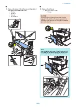
Page 165: ...5 Remove the idler gear 1 claw 1x 4 Disassembly Assembly 155 ...
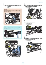
Page 172: ... 1 4 2 3 2 2 Remove the scanner motor 4 screws 4x 4 Disassembly Assembly 162 ...
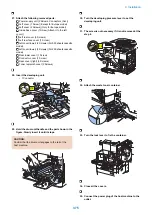
Page 186: ...3 Remove the RAM PCB Release the hook 4 Disassembly Assembly 176 ...
Page 187: ...Adjustment 5 Overview 178 Basic Adjustment 180 Adjustment when Replacing the Parts 182 ...
Page 209: ...Error Jam Alarm 7 Outline 200 Error Code 201 Jam Code 213 Alarm Code 219 ...
Page 231: ...Service Mode 8 Overview 222 Details of Service Mode 225 Remote UI Service Mode 302 ...
Page 314: ...Example of report display 8 Service Mode 304 ...
Page 387: ...APPENDICES Service Tools 378 General Circuit Diagram 379 ...