


NOTE:
The frequency and the output level of individual frequencies are in keeping with the output level set in service mode.
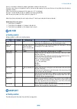
G3 Signal Transmission Test
A press on '4' on the keypad from the MODEM test menu selects the G3 signal transmission test.
In this test, the following G3 signals from the modem are transmitted using the telephone line terminal and the speaker.
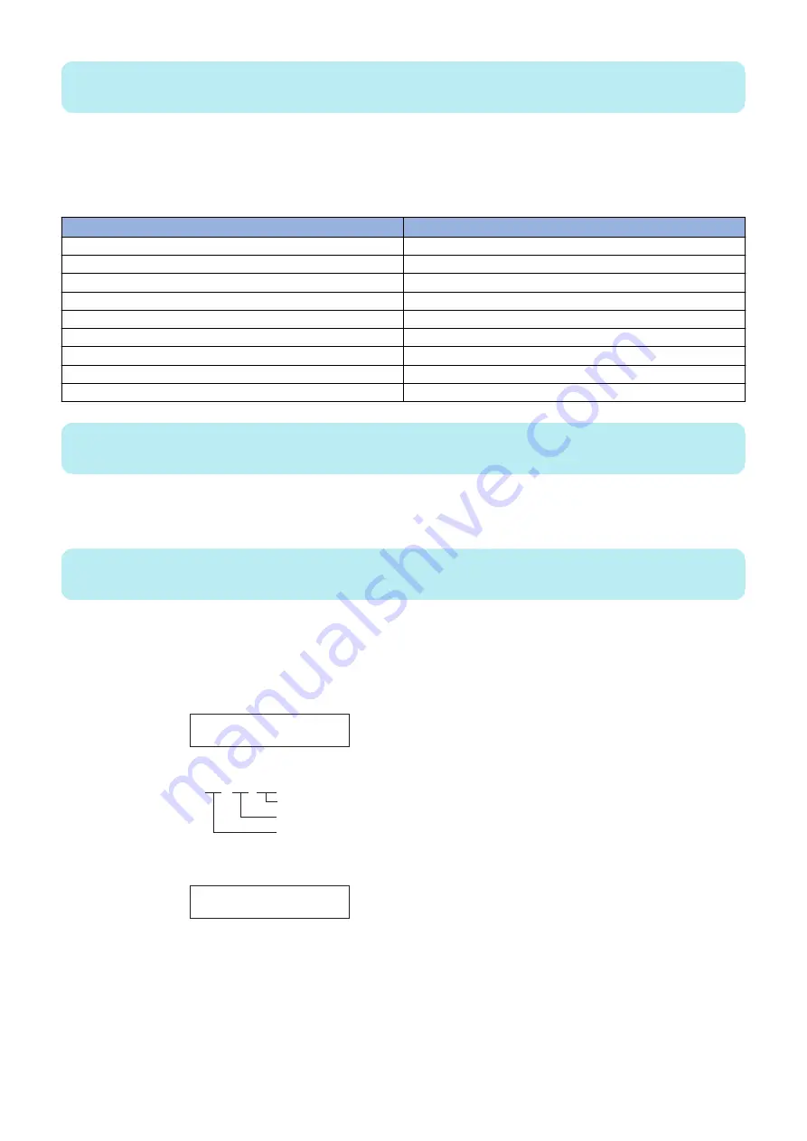
To select a different transmission speed, use the keypad.
Keypad
Transmission speed
0
300bps
1
2400bps
2
4800bps
3
7200bps
4
9600bps
5
TC7200bps
6
TC9600bps
7
12000bps
8
14400bps
NOTE:
The output level of individual signals is in keeping with the setting made in service mode.
A press on '5' on the MODEM test menu selects the DTMF signal transmission test. In the test, the following DTMF signals from
the modem are transmitted using the telephone line terminal and the speaker. The number pressed on the keypad selects a
specific DTMF signal.
NOTE:
The output level of individual signals is in keeping with the setting made in service mode.
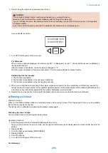
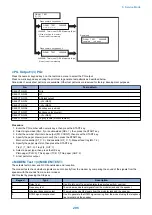
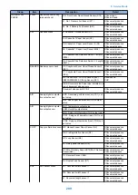
Tonal/DTMF Signal Reception Test
A press on '6' on the keypad from the MODEM test menu selects the tonal signal/DTMF signal reception 0 test. In this signal, the
tonal signal/DTMF signal received from the telephone line terminal can be checked to find out if it was detected by the modem.
MODEM TEST
OFF OFF OFF
OFF OFF OFF
changes from '0' to '1' in response to detection of a signal of 462±25Hz.
changes from '0' to '1' in response to detection of a signal of 1100±30Hz.
changes from '0' to '1' in response to detection of a signal of 2100±25Hz.
Tonal signal reception test
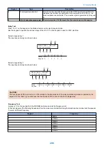
MODEM TEST
OFF OFF OFF 5
DTMF signal reception test
The received DTMF signals are indicated starting
from the right using the 2nd character of the display.
V.34 G3 Signal Transmission Test
A press on '8' on the keypad from the MODEM test menu selectes the V.34 G3 signal transmission test.
The V.34 G3 signals below are sent from the modem using the modular jack and the speaker by pressing the start key.
The Baud rate can be changed with the keypad, and the Speed can be changed with the left/right arrow key.
8. Service Mode
297
Summary of Contents for imageRUNNER 2525 Series
Page 1: ...Revision 9 0 imageRUNNER 2530 2525 2520 Series Service Manual ...
Page 62: ...No Part name 3 Laser unit 2 Technical Explanation 52 ...
Page 119: ...Periodical Service 3 Consumable Parts and Cleaning Parts 110 Cleaning Parts 115 ...
Page 125: ...Cleaning Parts Fixing guide Transfer guide 3 Periodical Service 115 ...
Page 136: ...List of Sensors S18 S17 S16 TS2 HU1 S9 S8 S19 TS1 S11 S12 4 Disassembly Assembly 126 ...
Page 165: ...5 Remove the idler gear 1 claw 1x 4 Disassembly Assembly 155 ...
Page 172: ... 1 4 2 3 2 2 Remove the scanner motor 4 screws 4x 4 Disassembly Assembly 162 ...
Page 186: ...3 Remove the RAM PCB Release the hook 4 Disassembly Assembly 176 ...
Page 187: ...Adjustment 5 Overview 178 Basic Adjustment 180 Adjustment when Replacing the Parts 182 ...
Page 209: ...Error Jam Alarm 7 Outline 200 Error Code 201 Jam Code 213 Alarm Code 219 ...
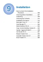
Page 231: ...Service Mode 8 Overview 222 Details of Service Mode 225 Remote UI Service Mode 302 ...
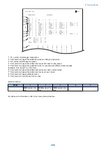
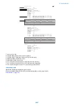
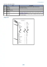
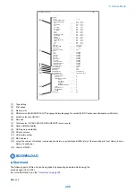
Page 314: ...Example of report display 8 Service Mode 304 ...
Page 387: ...APPENDICES Service Tools 378 General Circuit Diagram 379 ...