


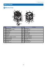


No.
Part name
No.
Part name
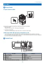
[7]
Additional Function key
[16]
Log in/Out key
[8]
Volume Control key
[17]
Numeric keys
[9]
Counter Check key
[18]
Reset key
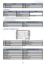
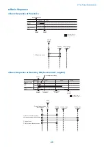
■ Main Menu
Functions
Key
Location
Copy
COPY key
Control Panel
Send or Fax
SEND key
Remote Scan
SCAN/OPTIONS key
System Monitor
[System Monitor]
Touch Panel Display
• The Send function is available only when the Color Send Kit-Y1 is activated.
• The Fax function is available only when the Super G3 Fax Board-AG1 is activated.
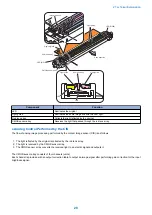
● Difference of main menu
imageRUNNER 2030/2025/2022/2018 Series
imageRUNNER 2530/2525/2520 Series
Copy
Copy
Send or Fax
Send or Fax
Scan
Scan or Direct print
System Monitor
System Monitor
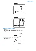
■ Settings / Registration menu
[6]
[7]
[8]
[9]
[1]
[2]
[3]
[4]
[5]
[1]
Common Settings
[6]
Copy Settings
[2]
Timer Settings
[7]
Communications Settings
[3]
Adjustment/Cleaning
[8]
Printer Settings
[4]
Report Settings
[9]
Address Book Settings
[5]
System Settings
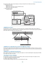
● Difference of Settings / Registration menu
imageRUNNER 2030/2025/2022/2018 Series
imageRUNNER 2530/2525/2520 Series
Common Settings
Common Settings
Timer Settings
Timer Settings
Adjustment/Cleaning
Adjustment/Cleaning
Report Settings
Report Settings
System Settings
System Settings
Copy Settings
Copy Settings
Communications Settings
Communications Settings
Printer Settings
Printer Settings
Address Book Settings
Address Book Settings
1. Product Overview
19
Summary of Contents for imageRUNNER 2525 Series
Page 1: ...Revision 9 0 imageRUNNER 2530 2525 2520 Series Service Manual ...
Page 62: ...No Part name 3 Laser unit 2 Technical Explanation 52 ...
Page 119: ...Periodical Service 3 Consumable Parts and Cleaning Parts 110 Cleaning Parts 115 ...
Page 125: ...Cleaning Parts Fixing guide Transfer guide 3 Periodical Service 115 ...
Page 136: ...List of Sensors S18 S17 S16 TS2 HU1 S9 S8 S19 TS1 S11 S12 4 Disassembly Assembly 126 ...
Page 165: ...5 Remove the idler gear 1 claw 1x 4 Disassembly Assembly 155 ...
Page 172: ... 1 4 2 3 2 2 Remove the scanner motor 4 screws 4x 4 Disassembly Assembly 162 ...
Page 186: ...3 Remove the RAM PCB Release the hook 4 Disassembly Assembly 176 ...
Page 187: ...Adjustment 5 Overview 178 Basic Adjustment 180 Adjustment when Replacing the Parts 182 ...
Page 209: ...Error Jam Alarm 7 Outline 200 Error Code 201 Jam Code 213 Alarm Code 219 ...
Page 231: ...Service Mode 8 Overview 222 Details of Service Mode 225 Remote UI Service Mode 302 ...
Page 314: ...Example of report display 8 Service Mode 304 ...
Page 387: ...APPENDICES Service Tools 378 General Circuit Diagram 379 ...