


Sym-
bol
Part name
Main unit
Reference
iR2530/2525 (550-sheet 1st cas-
sette type)
iR2530/2525/2520 (250-
sheet 1st cassette
type)
S33
Copyboard Cover Open/Closed Sensor 1
-
-
S34
Original Size Sensor 0
-
-
S35
Original Size Sensor 1
-
-
S36
Original Size Sensor 2
-
-
S37
Original Size Sensor 3
-
-
S40
Reversal Sensor
No.2 Deleivery Assembly
-
S41
No. 2 Delivery Full Sensor
No.2 Deleivery Assembly
-
S42
No. 2 Delivery Sensor
No.2 Deleivery Assembly
-
HU1
Environment Sensor
-
-
TS1
Developing Unit Toner Sensor
Developing Assembly
-
TS2
Sub Hopper Toner Sensor
Developing Assembly
-
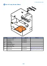
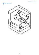
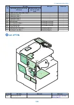
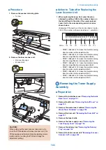
List of PCBs
PCB5d
PCB5c
PCB5b
PCB5a
PCB2
PCB3
PCB1
PCB13
PCB11
PCB7
PCB4
PCB6
PCB12
PCB14
PCB15
PCB16
PCB18
PCB10
PCB17
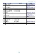
Symbol
Part name
Main unit
Reference
PCB1
Main Controller PCB
-
“Removing the Main Controller
PCB” on page 171
4. Disassembly/Assembly
128
Summary of Contents for imageRUNNER 2525 Series
Page 1: ...Revision 9 0 imageRUNNER 2530 2525 2520 Series Service Manual ...
Page 62: ...No Part name 3 Laser unit 2 Technical Explanation 52 ...
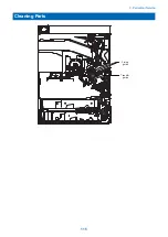
Page 119: ...Periodical Service 3 Consumable Parts and Cleaning Parts 110 Cleaning Parts 115 ...
Page 125: ...Cleaning Parts Fixing guide Transfer guide 3 Periodical Service 115 ...
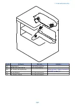
Page 136: ...List of Sensors S18 S17 S16 TS2 HU1 S9 S8 S19 TS1 S11 S12 4 Disassembly Assembly 126 ...
Page 165: ...5 Remove the idler gear 1 claw 1x 4 Disassembly Assembly 155 ...
Page 172: ... 1 4 2 3 2 2 Remove the scanner motor 4 screws 4x 4 Disassembly Assembly 162 ...
Page 186: ...3 Remove the RAM PCB Release the hook 4 Disassembly Assembly 176 ...
Page 187: ...Adjustment 5 Overview 178 Basic Adjustment 180 Adjustment when Replacing the Parts 182 ...
Page 209: ...Error Jam Alarm 7 Outline 200 Error Code 201 Jam Code 213 Alarm Code 219 ...
Page 231: ...Service Mode 8 Overview 222 Details of Service Mode 225 Remote UI Service Mode 302 ...
Page 314: ...Example of report display 8 Service Mode 304 ...
Page 387: ...APPENDICES Service Tools 378 General Circuit Diagram 379 ...