
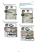


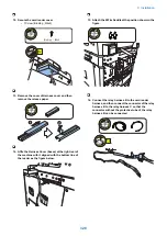


7. Connect the RS Conversion PCB and the CV-Serial
Relay Cable, and install the RS232C Support Plate
by aligning the 2 Protrusions on the plate with the
holes on the host machine.
• 2 Screws (TP; M3x6)
• 2 Protrusions
• 2 Holes
Protrusion
Protrusion
Hole
Hole
2x
1x
TP ; M3X6
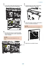
8. Be sure to put the harness [A] between the RS
Conversion PCB and the plate [B] with the tie-wrap
[C] of it on the front side.
[A]
[C]
[B]
[A]
[B]
[A]
[C]
[B]
[A]
[B]
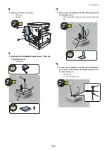
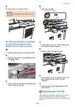
9. Install the Controller Cover.
10. Install the Rear Cover (Right).
11. Install the Power Plug.
12. Install the Power Supply Retainer.
13. Turn ON the main power switch.
9. Installation
334
Summary of Contents for imageRUNNER 2525 Series
Page 1: ...Revision 9 0 imageRUNNER 2530 2525 2520 Series Service Manual ...
Page 62: ...No Part name 3 Laser unit 2 Technical Explanation 52 ...
Page 119: ...Periodical Service 3 Consumable Parts and Cleaning Parts 110 Cleaning Parts 115 ...
Page 125: ...Cleaning Parts Fixing guide Transfer guide 3 Periodical Service 115 ...
Page 136: ...List of Sensors S18 S17 S16 TS2 HU1 S9 S8 S19 TS1 S11 S12 4 Disassembly Assembly 126 ...
Page 165: ...5 Remove the idler gear 1 claw 1x 4 Disassembly Assembly 155 ...
Page 172: ... 1 4 2 3 2 2 Remove the scanner motor 4 screws 4x 4 Disassembly Assembly 162 ...
Page 186: ...3 Remove the RAM PCB Release the hook 4 Disassembly Assembly 176 ...
Page 187: ...Adjustment 5 Overview 178 Basic Adjustment 180 Adjustment when Replacing the Parts 182 ...
Page 209: ...Error Jam Alarm 7 Outline 200 Error Code 201 Jam Code 213 Alarm Code 219 ...
Page 231: ...Service Mode 8 Overview 222 Details of Service Mode 225 Remote UI Service Mode 302 ...
Page 314: ...Example of report display 8 Service Mode 304 ...
Page 387: ...APPENDICES Service Tools 378 General Circuit Diagram 379 ...